Method for visual positioning calibration and corresponding numerical control machining method
A technology for visual positioning and processing of workpieces, applied in metal processing equipment, metal processing mechanical parts, manufacturing tools, etc., can solve the problems of error, large error, pixel and distance proportional relationship error, etc., to achieve less deviation, easy operation, and realization of The effect of calibration
- Summary
- Abstract
- Description
- Claims
- Application Information
AI Technical Summary
Problems solved by technology
Method used
Image
Examples
Embodiment 1
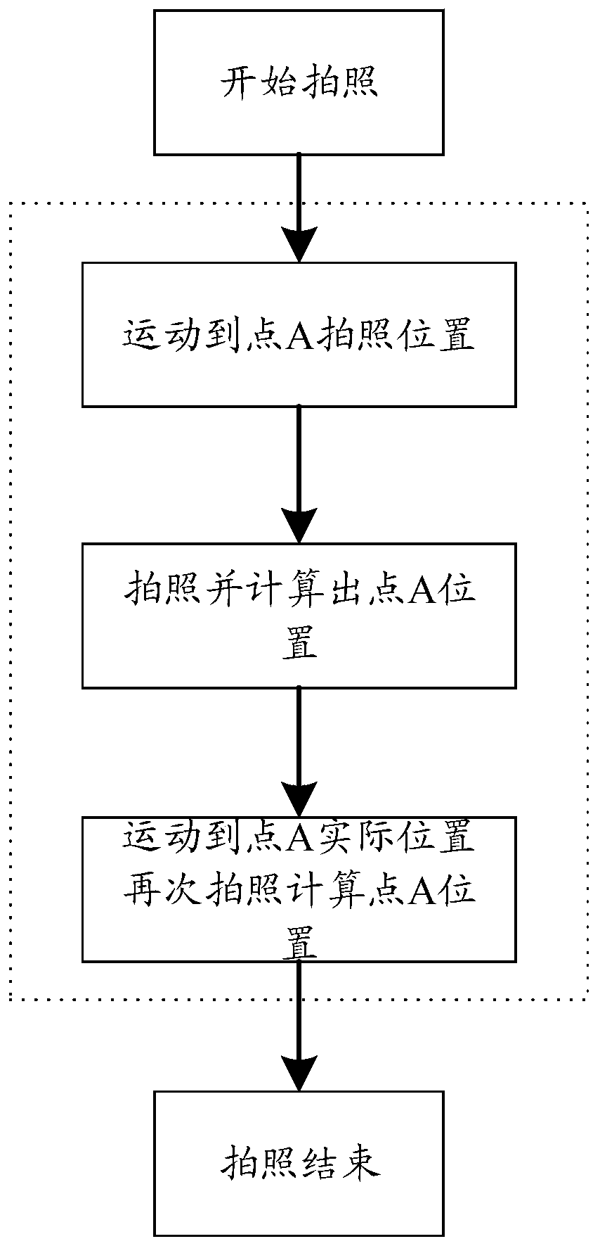
[0057] 1. During operation, the CNC machine tool first moves the shooting device to the shooting point (that is, the system preset shooting position), takes a picture and calculates the position of the point, and converts the offset pixel of the feature point A into the offset distance;
[0058] (Assume that point A is offset by 200 pixels from the center of the camera when point A is photographed in step 1, the ratio between pixels and displacement is 100:1, and the final offset is 2 mm. Because of the proportional relationship between pixels and distance There is an error, assuming that the error is 1%, then the actual position here is 2 mm, then the error caused by the conversion here is ≈0.02 mm.)
[0059] 2. The CNC machine tool moves the shooting equipment to a new photo point to take pictures. The coordinates of the new photo point = the coordinates of the photo point + the offset distance. At this time, when taking pictures, point A is only 0.02mm away from the center o...
Embodiment 2
[0061] 1. First set the camera position, for example, X=10, Y=10
[0062] 2. According to the coordinates X and Y of the system preset shooting position, move the camera to the position set in step 1. After taking a picture, the offset of the feature point is X=200 pixels, Y=300 pixels. Assume that the proportional relationship between pixels and distance is 100 pixels = 1 mm. Then the actual position of this feature point X=12, Y=13
[0063] Because there is an error in the proportional relationship between the pixel and the distance, it is assumed that the actual proportional relationship is 99 pixels = 1 mm. At this time, the actual position of the feature point is X=12.02, Y=13.03
[0064] 3. If you directly use the position in the above step 2 as the actual point position at this time, then the X error here is 0.02, and the Y error is 0.03. If the machine tool is transported to the position of X=12 and Y=13 at this time, go to Take a picture, at this time you can get ...
PUM
 Abstract
Description
Claims
Application Information
 - R&D
- Intellectual Property
- Life Sciences
- Materials
- Tech Scout
- Unparalleled Data Quality
- Higher Quality Content
- 60% Fewer Hallucinations
Browse by: Latest US Patents, China's latest patents, Technical Efficacy Thesaurus, Application Domain, Technology Topic, Popular Technical Reports.
© 2025 PatSnap. All rights reserved.Legal|Privacy policy|Modern Slavery Act Transparency Statement|Sitemap|About US| Contact US: help@patsnap.com


