
Ship segmented outer plate and aggregate positioning method

A positioning method and bone material technology, applied to ships and other directions, can solve the problems of large cumulative error, repair workload, and low efficiency, and achieve the effects of reducing welding deformation, improving positioning accuracy, and improving production efficiency

Active Publication Date: 2020-01-17
GUANGZHOU WENCHONG SHIPYARD CO LTD
View PDF6 Cites 4 Cited by
  • Summary
  • Abstract
  • Description
  • Claims
  • Application Information

AI Technical Summary

Problems solved by technology

[0002] In the process of ship construction, the section with larger outer plate line shape and relatively empty structure accounts for about 30% to 40% of the whole ship, and this type of section is the most difficult to control the accuracy and quality of the entire ship section construction process The production cycle and labor cost are also the longest, and the root cause of this problem is that the precise assembly and positioning of curved outer plates and longitudinal bulk aggregates is more difficult
At present, in the production process, construction personnel mainly use partial structural relative data to locate the outer panels and aggregates. During the positioning process, they need to be measured and rechecked one by one. The above-mentioned construction method of measuring while installing has the following problems: low efficiency and large cumulative errors , and it is easy to deform after welding, resulting in the workload of rework

Method used


Image

  • Ship segmented outer plate and aggregate positioning method
  • Ship segmented outer plate and aggregate positioning method
  • Ship segmented outer plate and aggregate positioning method

Examples


Embodiment Construction

[0026] This part will describe the specific embodiment of the present invention in detail, and the preferred embodiment of the present invention is shown in the accompanying drawings. Each technical feature and overall technical solution of the invention, but it should not be understood as a limitation on the protection scope of the present invention.

[0027] In the description of the present invention, it should be understood that the orientation descriptions, such as up, down, front, back, left, right, etc. indicated orientations or positional relationships are based on the orientations or positional relationships shown in the drawings, and are only In order to facilitate the description of the present invention and simplify the description, it does not indicate or imply that the device or element referred to must have a specific orientation, be constructed and operated in a specific orientation, and thus should not be construed as limiting the present invention.

[0028] I...


PUM


Abstract

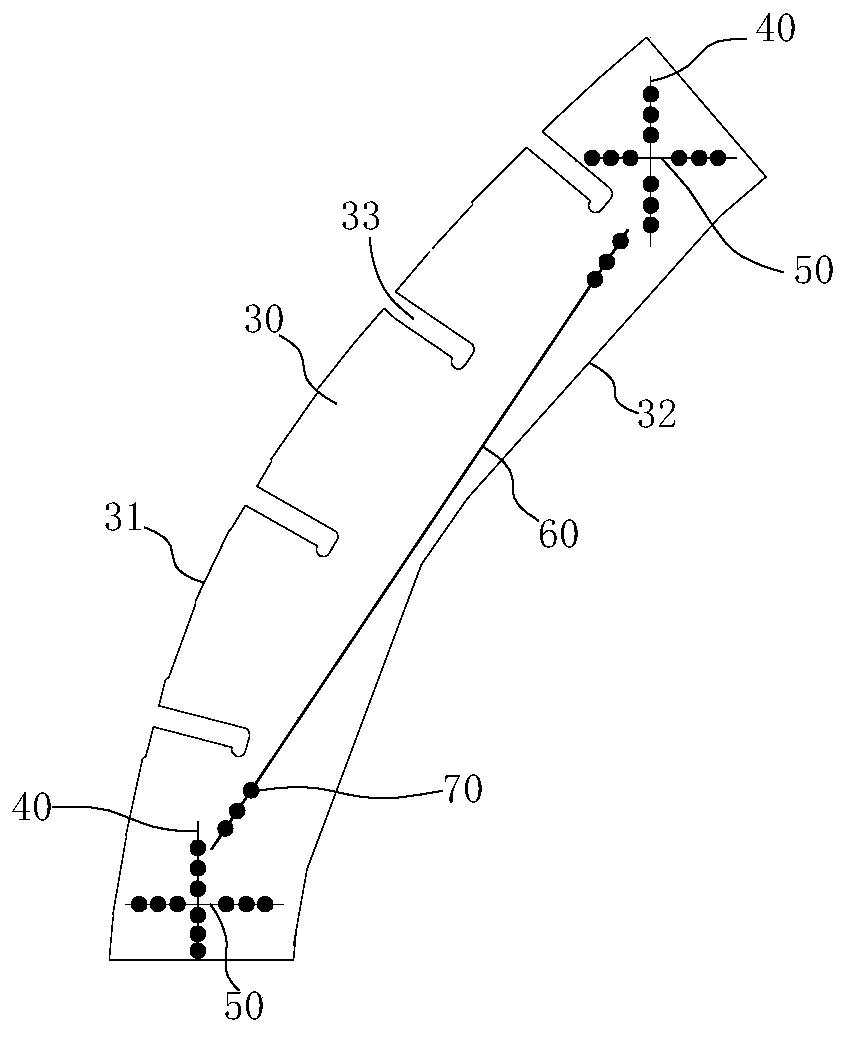
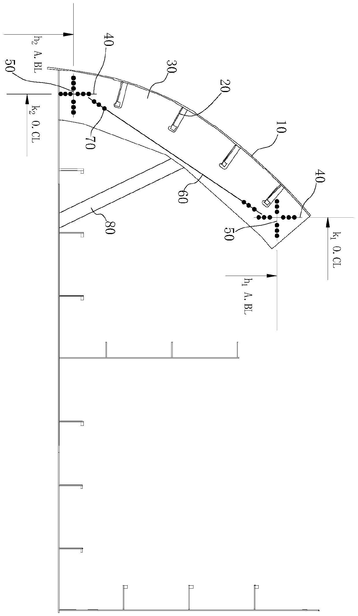
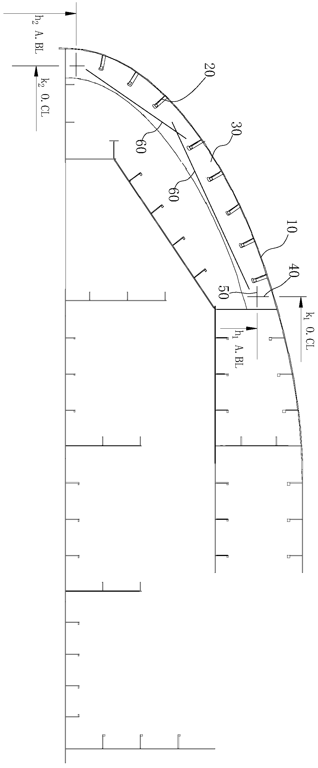
The invention discloses a ship segmented outer plate and aggregate positioning method. The method comprises the following steps: designing and cutting to obtain a tool plate, scribing lines on the tool plate, including an auxiliary half-width line and an auxiliary height line, then assembling a jig frame base surface and a longitudinal wall plate, mounting the tool plate by taking the jig frame base surface and the longitudinal wall plate as reference, checking the verticality of the tool plate relative to the jig frame base surface, and finally hoisting and welding aggregates and an outer plate. According to the invention, the tool plate is provided with an outer edge attached to the surface of the inner side of the outer plate and a through hole allowing aggregate to penetrate through. Therefore, the outer plate and the aggregate can be quickly positioned; the tool plate is positioned through the auxiliary half-width line and the auxiliary height line; compared with a traditional construction method, the positioning difficulty is lowered, the positioning precision is improved, accurate and rapid positioning of the ship segmented outer plate and the aggregate is achieved, the production efficiency is improved, the positions of the outer plate and the aggregate are fixed through the tool plate, welding deformation of the outer plate and the aggregate is reduced, and the methodis applied to the field of ship manufacturing.

Description

technical field [0001] The invention relates to the field of shipbuilding, in particular to a method for locating a segmented outer plate and a frame of a ship. Background technique [0002] In the process of ship construction, the section with larger outer plate line shape and relatively empty structure accounts for about 30% to 40% of the whole ship, and this type of section is the most difficult to control the accuracy and quality of the entire ship section construction process The production cycle and labor cost are also the longest, and the root cause of this problem is that the precise assembly and positioning of curved outer plates and longitudinal bulk aggregates is more difficult. At present, in the production process, construction personnel mainly use partial structural relative data to locate the outer panels and aggregates. During the positioning process, they need to be measured and rechecked one by one. The above-mentioned construction method of measuring while...

Claims


Application Information

Patent Timeline
IPC IPC(8): B63B73/00
Inventor 李解为姚成强曾仰德
Owner GUANGZHOU WENCHONG SHIPYARD CO LTD
Features
  • Generate Ideas
  • Intellectual Property
  • Life Sciences
  • Materials
  • Tech Scout
  • Unparalleled Data Quality
  • Higher Quality Content
  • 60% Fewer Hallucinations
Learn More