
Power device and aircraft

A technology for power devices and aircraft, applied in the field of power devices and aircraft, can solve the problems of increasing motor drive load, shortening motor life, and large motor load, etc., to achieve the effect of reducing speed fluctuations, prolonging motor life, and reducing motor load

Active Publication Date: 2020-01-17
ZHUHAI PANSHI ELECTRONICS TECH CO LTD
View PDF4 Cites 2 Cited by
  • Summary
  • Abstract
  • Description
  • Claims
  • Application Information

AI Technical Summary

Problems solved by technology

However, the setting of the duct increases the weight of the flying device and increases the driving load of the motor, which can easily cause the motor load to be too large. Moreover, under different working conditions, the speed of the motor needs to be changed frequently and greatly, which shortens the life of the motor and reduces the overall performance of the motor. work efficiency

Method used


Image

  • Power device and aircraft
  • Power device and aircraft
  • Power device and aircraft

Examples


Embodiment Construction

[0029] power plant embodiment

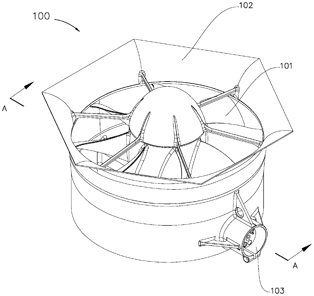
[0030] like figure 1 As shown, the power plant 100 includes a propeller 101 and a duct 102 . The duct 102 is provided with a power input port 103 .

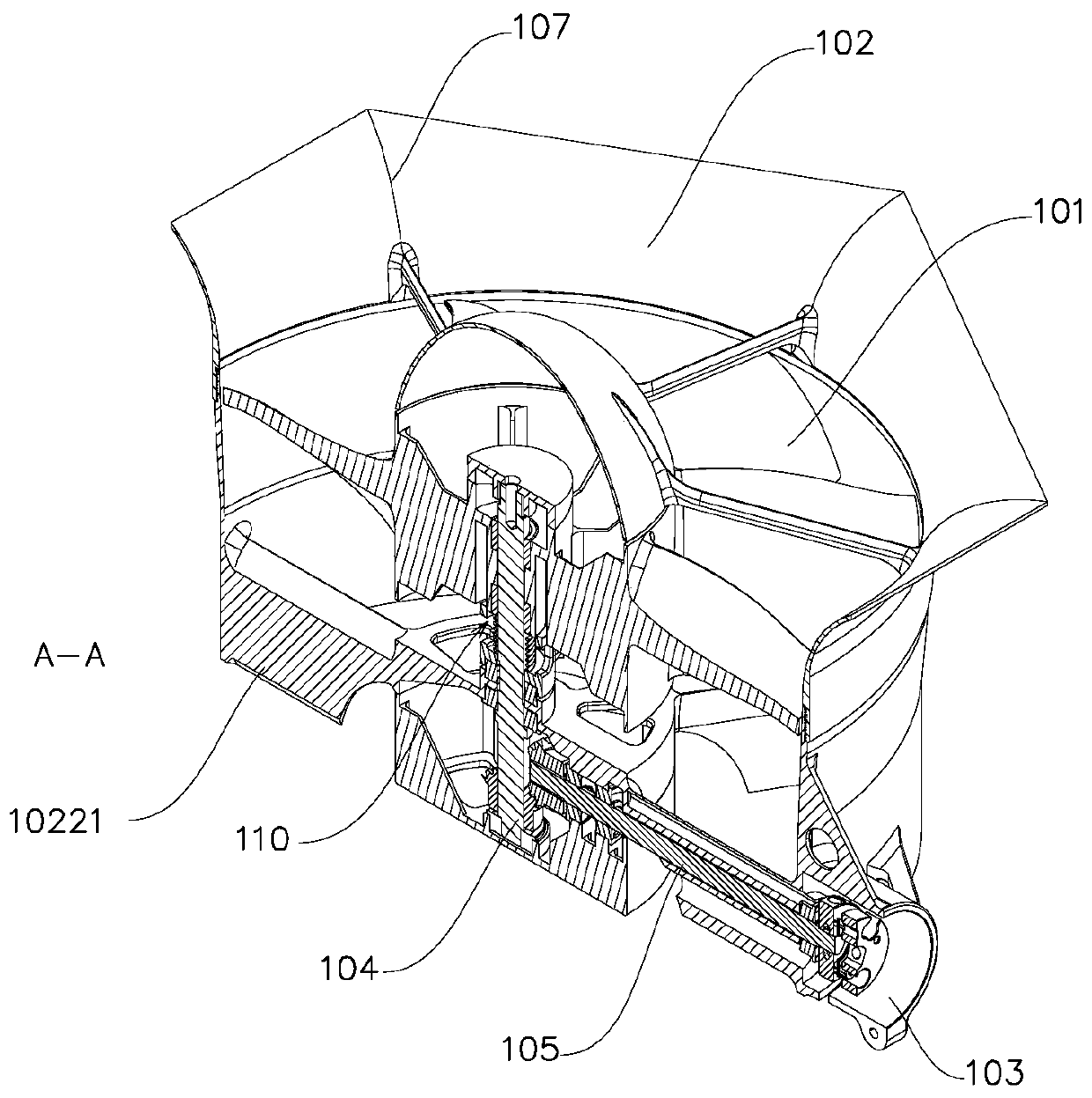
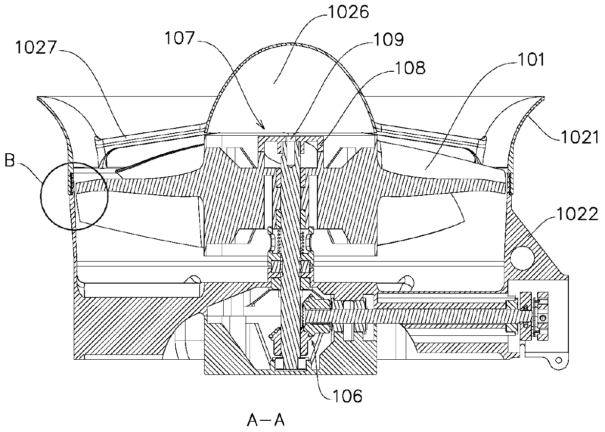
[0031] according to figure 2 , image 3 and Figure 4 From a comprehensive analysis, the duct 102 includes a radially outward arc lip 1021 of the air inlet and a duct barrel 1022 . The arc-shaped lip 1021 is fixed to the duct tube 1022 through threads 1023 . The inner wall of the arc-shaped lip 1021 is a tapered surface 1024 . Guide grooves 1025 are evenly distributed along the circumferential direction of the arc-shaped lip 1021 . The fairing 1026 is fixed on the arc-shaped lip 1021 through the ribs 1027 evenly distributed along the circumferential direction of the arc-shaped lip 1021 .

[0032] The propeller 101 is slidably installed in the duct tube 1022 through the rotating shaft 104 . At the end of the duct tube 1022 away from the air inlet, a predetermined number of straightening pl...


PUM


Abstract

The invention provides a power device. The power device comprises a propeller, a duct and a driving unit. The propeller is rotatably installed in the duct, and the driving unit drives the propeller torotate. The inner wall of the duct is of a conical structure; the propeller is mounted in the duct in a sliding manner; and the sliding control device drives the propeller to slide along the rotatingaxis. The sliding control device drives the propeller to slide, and the thrust output of the duct can be adjusted by adjusting the propeller duct gap between the blade tip of the blade and the conical inner wall of the duct. The motor does not need to control power output of the power device through large-amplitude frequent acceleration and deceleration, thereby effectively reducing motor rotating speed fluctuation amplitude, reducing motor load and prolonging service life of the motor. The working efficiency of the power device is improved.

Description

technical field [0001] The invention relates to a power device and an aircraft with the power device. Background technique [0002] Today's power plants are mostly composed of propellers. When the propeller moves, the main resistances are air friction resistance, pressure difference resistance, induced resistance and interference resistance. Due to the high-speed circular motion of the blade, the speed at the blade tip is the highest, the induced resistance is relatively large, and the impact on the external airflow causes large noise, which is the main reason for the low power efficiency of the free propeller. [0003] The ducted fan propeller is a power device in which ducts are arranged around the propeller to solve existing problems. The blade tip of the propeller is limited by the duct, and the impact noise is reduced. Induced drag is reduced and efficiency is higher. Under the same power consumption, ducted fans can generate greater thrust than isolated propellers ...

Claims


Application Information

Patent Timeline
IPC IPC(8): B64C11/00B64C27/20
CPCB64C11/001B64C27/20
Inventor 何春旺
Owner ZHUHAI PANSHI ELECTRONICS TECH CO LTD
Learn More