
A Drilling Drawworks Valve Box Control System

A control system and valve box technology, applied in the direction of valve lift, valve details, valve device, etc., can solve the problems of damage control function and failure of electrical components, and achieve the effect of maintaining explosion-proof performance

Active Publication Date: 2020-11-20
BAOJI PETROLEUM MASCH CO LTD +2
View PDF9 Cites 0 Cited by
  • Summary
  • Abstract
  • Description
  • Claims
  • Application Information

AI Technical Summary

Problems solved by technology

[0003] The purpose of the present invention is to provide a drilling winch valve box control system, which solves the problem of damage to electrical components and failure of control functions in the prior art due to water accumulation in the explosion-proof valve box of the drawworks

Method used


Image

  • A Drilling Drawworks Valve Box Control System
  • A Drilling Drawworks Valve Box Control System
  • A Drilling Drawworks Valve Box Control System

Examples


Embodiment Construction

[0027] The present invention will be described in detail below in conjunction with the accompanying drawings and specific embodiments.

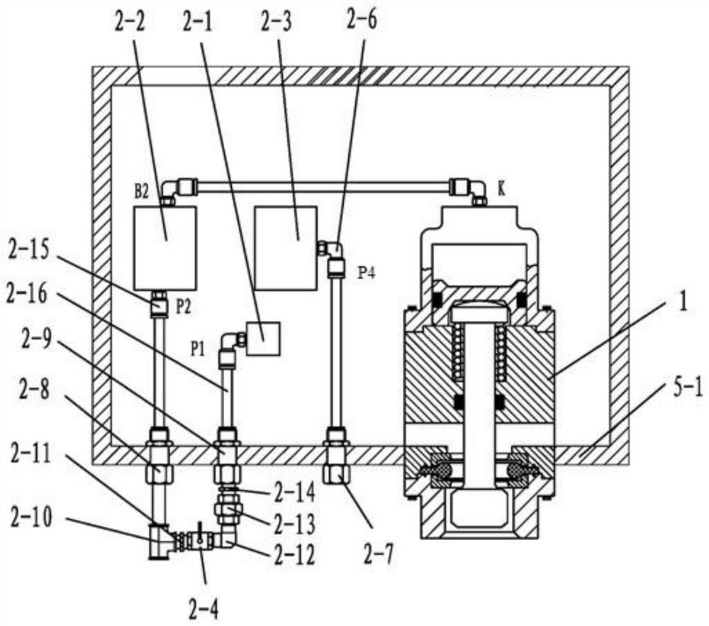
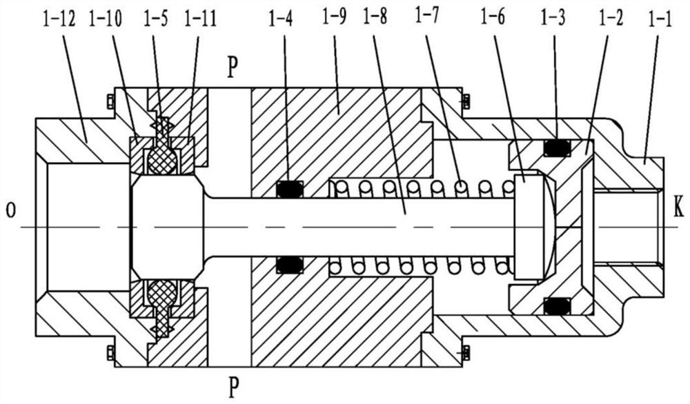
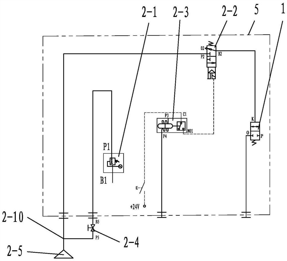
[0028] The invention provides a drilling winch valve box control system, such as figure 1 As shown, the drain valve 1 is installed vertically in the valve box 5, the lower edge of the drain inlet P on the middle cover 1-9 of the drain valve 1 is flush with the inner edge of the valve box bottom plate 5-1, and the middle cover 1-9 9 is welded with the inner and outer intersections of the valve box bottom plate 5-1, the drainage inlet P of the drain valve 1 is directly opened in the box body of the valve box 5, and the drainage outlet O of the drain valve 1 is opened outside the valve box 5 and connected to the atmosphere In communication, the fourth air inlet P4 of the differential pressure switch 2-3 is connected to the first wall joint 2-7 through the first pipeline joint 2-6, and the first wall joint 2-7 is connected to the inside and outsi...


PUM


Abstract

The invention discloses a control system for a valve cage of a drilling winch. The control system comprises a drain valve arranged on a bottom plate of the valve cage, and the side part of the drain valve communicates with the inner part of the valve cage. One end of the drain valve extends downward out of the valve cage, and the other end of the drain valve is positioned in the valve cage and communicates with a pneumatic control unit through a pipeline. The pneumatic control unit is connected with an electronic control unit through a conducting wire. According to the control system for the valve cage of the drilling winch, solenoid valves are arranged in a control port loop of the drain valve, and the on and off of the corresponding solenoid valve is automatically controlled by setting adetection setting value of a low voltage differential switch and using the low voltage differential switch and a gas-electric conversion switch by, so that the start and stop of drainage of the drainvalve is automatically controlled. Thus, the function of automatic drainage on demand of the drain valve is realized, the outside gas of the valve cage is prevented from entering the valve cage, theexplosion-proof performance of the valve cage is maintained, and drainage can be started and stopped in real time as needed.

Description

technical field [0001] The invention belongs to the technical field of mechanical control of petroleum drilling winches, and in particular relates to a valve box control system of a drilling winch. Background technique [0002] The existing variable frequency drilling rig with the winch installed at a high position on the drilling floor, because the drawworks valve box is installed in or close to the explosion-proof area, in order to respond to HSE safety requirements, more and more users require the overall explosion-proof of the winch control valve box, and the valve box The overall protection level is above IP56, with high sealing performance. The winch valve box is integrated with solenoid valves for controlling the action of winch pneumatic actuators and disc brakes, signal feedback detection components (including: pressure switch, pressure sensor), terminal blocks, etc. Electrical components, drilling rigs are often opened during commissioning or maintenance. If it rai...

Claims


Application Information

Patent Timeline
Patent Type & Authority Patents(China)
IPC IPC(8): B66D1/40F16K31/122F16K31/02F16K1/00H01H35/24
CPCB66D1/40F16K1/00F16K31/02F16K31/1221H01H35/24
Inventor 蒋合艳李亚辉赵博郭乾坤刘晓峰陆俊康
Owner BAOJI PETROLEUM MASCH CO LTD
Learn More