Construction method of cast-in-place pile

A construction method and technology of cast-in-situ piles, which are applied in sheet pile walls, foundation structure engineering, construction, etc., can solve the problems of reducing concrete strength, concrete leakage, loose soil and sand and gravel filling coefficient, etc., to reduce filling coefficient, prevent leakage, enhance the effect of strength

Active Publication Date: 2020-01-17
江西思绮建筑工程有限公司
View PDF6 Cites 2 Cited by
  • Summary
  • Abstract
  • Description
  • Claims
  • Application Information

AI Technical Summary

Problems solved by technology

[0004] Although the current hole-forming method of the auger drilling machine can realize drilling and pouring more conveniently, the inner wall of the pile hole completed by this construction method is relatively loose soil and sandstone, which leads to pouring into the pile hole. When the casing casing is pulled out from the concrete side, due to the large filling coefficient of the l

Method used


Image

  • Construction method of cast-in-place pile
  • Construction method of cast-in-place pile

Examples


Embodiment 1

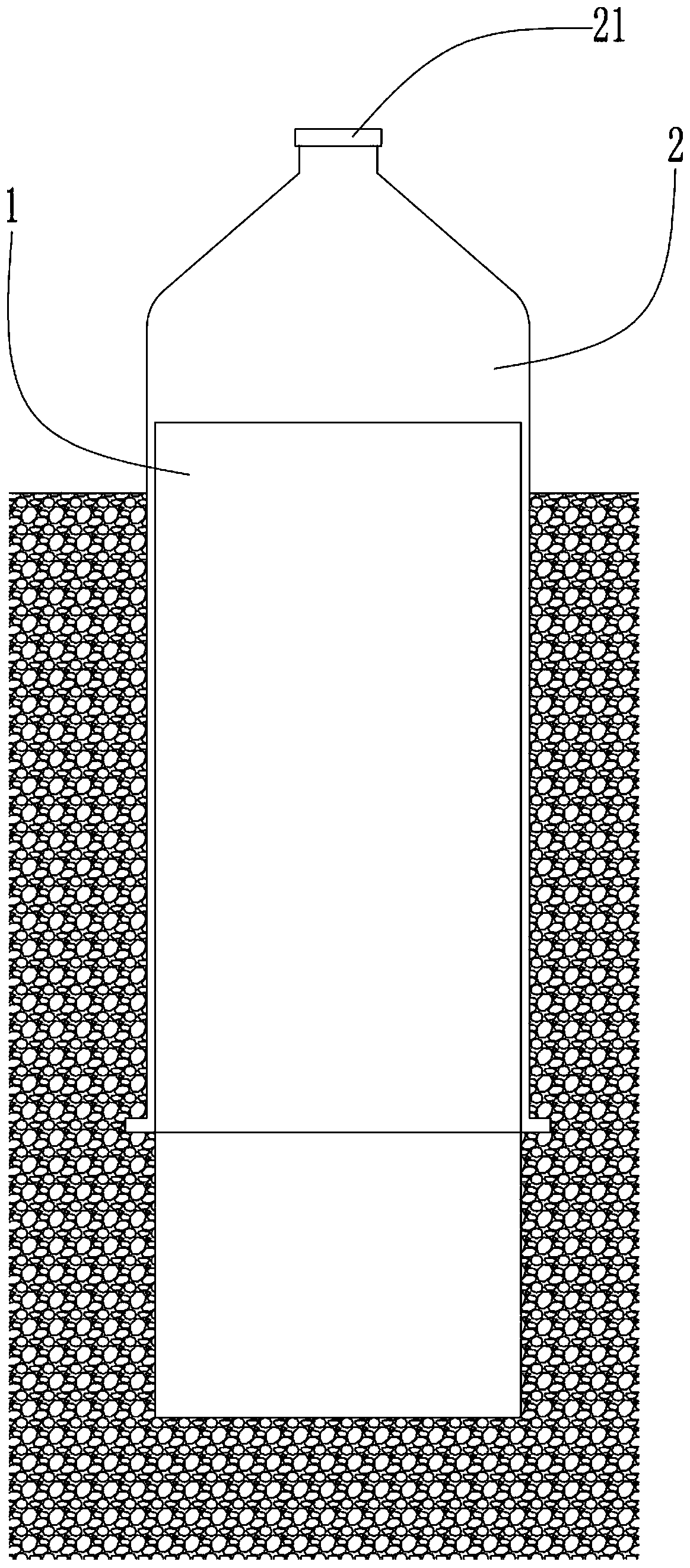
[0020] The specific steps of construction in this specific embodiment are as follows: firstly, on the ground position of the designed cast-in-situ pile, the casing casing is driven into the ground 5m by a hydraulic vibratory hammer, and the soil and sand in the casing casing are dug out by an auger drill , to form a pile hole; then install a shock guide on the outer casing of the casing casing, so that the inner diameter of the shock guide fits the outer diameter of the casing casing, and connect the shock guide to the hydraulic vibrating hammer. The hydraulic vibrating hammer vibrates and squeezes the vibrating guide downward along the casing casing and penetrates deep into the ground, so that the vibration guide moves the soil outside the casing casing and Sand and gravel are crushed and compacted, the vibration frequency of the hydraulic vibrating hammer is controlled to 2500 rpm, the pressure of the hydraulic vibrating hammer is controlled to 70 tons, and then the vibrating...

Embodiment 2

[0022] The specific steps of construction in this specific embodiment are as follows: firstly, on the ground position of the designed cast-in-place pile, the casing casing is driven into the ground 6m by a hydraulic vibratory hammer, and the soil and sand in the casing casing are dug out by an auger drill , to form a pile hole; then install a shock guide on the outer casing of the casing casing, so that the inner diameter of the shock guide fits the outer diameter of the casing casing, and connect the shock guide to the hydraulic vibrating hammer. The hydraulic vibrating hammer vibrates and squeezes the vibrating guide downward along the casing casing and penetrates deep into the ground, so that the vibration guide moves the soil outside the casing casing and Sand and gravel are crushed and compacted. Control the vibration frequency of the hydraulic vibrating hammer to 3000 rpm and control the pressure of the hydraulic vibrating hammer to 50 tons. Afterwards, put the reinforce...

Embodiment 3

[0024] The specific steps of construction in this specific embodiment are as follows: firstly, on the ground position of the designed cast-in-place pile, the casing casing is driven into the ground 8m by a hydraulic vibrating hammer, and the soil and sand in the casing casing are dug out by an auger drill , to form a pile hole; then install a shock guide on the outer casing of the casing casing, so that the inner diameter of the shock guide fits the outer diameter of the casing casing, and connect the shock guide to the hydraulic vibrating hammer. The hydraulic vibrating hammer vibrates and squeezes the vibrating guide downward along the casing casing and penetrates deep into the ground, so that the vibration guide moves the soil outside the casing casing and Sand and gravel are crushed and compacted, the vibration frequency of the hydraulic vibrating hammer is controlled to 3500 rpm, the pressure of the hydraulic vibrating hammer is controlled to 40 tons, and then the vibratin...


PUM


Abstract

The invention discloses a construction method of a cast-in-place pile, and aims to solve the technical problem that in the prior art, due to the fact that the filling coefficient of the side wall in apile hole of a cast-in-place pile is large, concrete leaks too much to the side wall in the pile hole, and the strength of the cast-in-place pile is reduced. The construction method comprises the following steps: driving a casing protection barrel underground at the ground position where the cast-in-place pile is designed, and digging out soil and sand in the casing protection barrel; then vibrating and extruding a vibration guide downwards along the casing protection barrel to penetrate into the underground through a hydraulic vibration hammer, and then taking out the vibration guide to supplement soil and compact the soil; and then, placing a reinforcement cage in the pile hole, pouring concrete into the middle of the pile hole and pulling out the casing protection barrel, completely pulling out the casing protection barrel after the pouring of the concrete is finished, and finishing the construction of the cast-in-place pile after the concrete is completely solidified. According tothe construction method, the filling coefficient of the periphery of the side wall in the pile hole can be greatly reduced, excessive outward leakage of concrete in the pile hole is prevented, and the strength of the cast-in-place pile is improved.

Description

technical field [0001] The invention belongs to a building construction method, in particular to a construction method of cast-in-situ piles. Background technique [0002] The cast-in-situ pile is a kind of construction body used in urban buildings. It is formed by directly opening a hole on the designed pile position with a circular cross-section. After the hole is formed, a steel cage is placed in the hole and concrete is poured. Cast-in-situ piles have been widely used in construction due to their advantages of no vibration, no soil extrusion, low noise, and suitable for use in densely built urban areas during construction. [0003] Cast-in-situ piles can be divided into cast-in-place piles with dry operation, cast-in-place piles with mud retaining walls, and cast-in-place piles with manual digging according to the hole-forming process; cast-in-place piles can be divided into Immersed tube cast-in-situ piles, bored cast-in-place piles, manual digging cast-in-place piles,...

Claims


Application Information

Patent Timeline
IPC IPC(8): E02D5/34E02D5/38E02D7/18
CPCE02D5/34E02D5/38E02D5/385E02D7/18
Inventor 刘岳林
Owner 江西思绮建筑工程有限公司
Why Eureka
Try Eureka