Prefabricated rail top air duct for metro station and construction method of air duct

A technology for rail top air ducts and subway stations, which is applied in mine/tunnel ventilation, earthwork drilling, mining equipment, etc. It can solve problems such as difficult pouring and compaction, affecting the construction period of the whole line, and difficult construction, so as to facilitate transportation and hoisting , save the amount of concrete, no need for post-maintenance effect

Pending Publication Date: 2020-01-17
JIANHUA CONSTR MATERIALS (CHINA) CO LTD
View PDF2 Cites 2 Cited by
  • Summary
  • Abstract
  • Description
  • Claims
  • Application Information

AI Technical Summary

Problems solved by technology

[0003] (1) The clearance height of the air duct on the top of the rail is less than 1 meter, so it is very difficult to erect formwork and bind steel bars;
[0004] (2) It is difficult to pour the hanging wall of the air duct on the top of the rail, and it is difficult to pour it densely. For the top-hung screen door, the positioning of the air duct civil construction is required to be controlled within 10mm. If the construction accuracy cannot be achieved, the rectification is particularly difficult;
[0005] (3) After the construction of the main structure inside the station is completed, the secondary structural construction of the rail top air duct needs to be carried out, and the civil engineering needs to enter the site again. At the same time, the electromechanical installation, station decoration and track construction also enter the site, and there will be cross operations, which will affect the construction period of the whole line
[0007] (1) The key connection nodes under permanent force are connected by steel structure, which has the problem of anti-corrosion and

Method used


Image

  • Prefabricated rail top air duct for metro station and construction method of air duct
  • Prefabricated rail top air duct for metro station and construction method of air duct
  • Prefabricated rail top air duct for metro station and construction method of air duct

Examples


Example Embodiment

[0070] Example 1

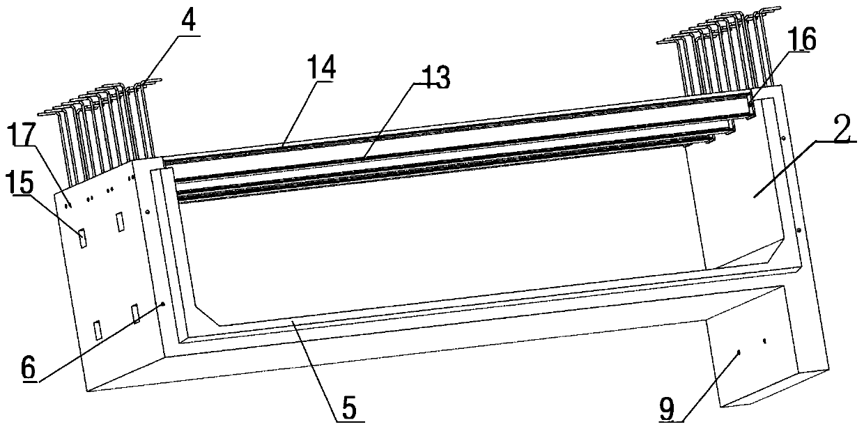
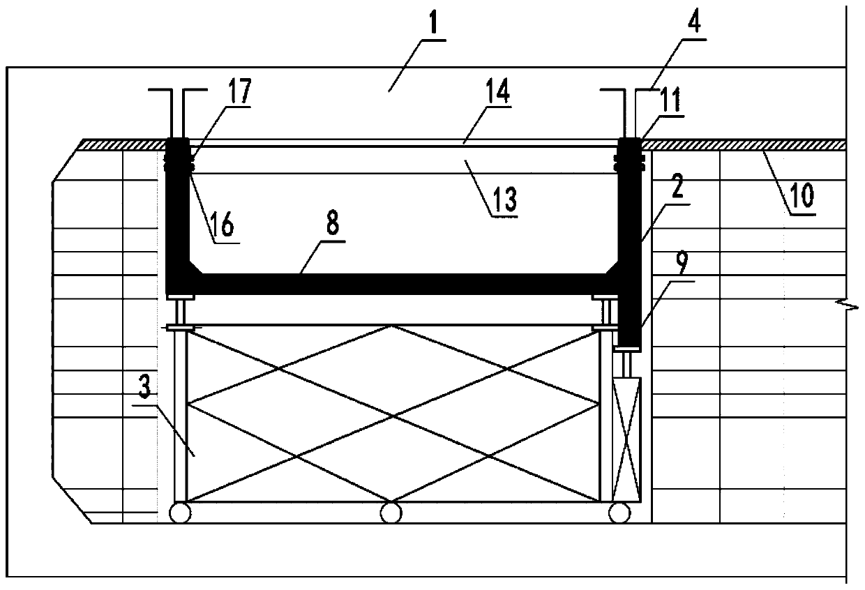
[0071] figure 1 with figure 2 It is a front view and a rear view of a rail-top air duct of the present invention. The air duct on the top of the prefabricated rail includes a U-shaped air duct 2. The inner bottom plate of the duct and the two side plates are integrally formed, and the top of the air duct side plate is reserved with steel bars 4, which can be bent into an "L" shape or inside Hollow rebar connector. The air duct port is composed of an air duct bottom plate and two side plates, which has two end faces. One end of the air duct port is left with a protruding structure 5 extending outward, and the other end of the air duct port is provided with a first groove 18 corresponding to the protruding structure 5, so that the protruding structure 5 can be inserted into the first The groove 18 is also provided with a second groove 19 in the shape of a "mouth" inside the first groove 18 for filling the composite rubber sealing strip.

[0072] A hole 9 connec...

Example Embodiment

[0089] Example 2

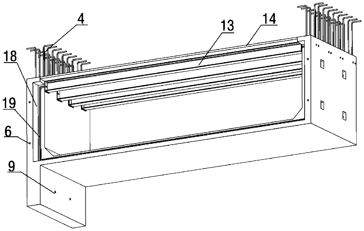
[0090] Such as Image 6 Shown is a schematic structural diagram of the second embodiment of the present invention. The prefabricated rail top air duct includes side plates, bottom plates and partition walls 20. The side plates, bottom plates and partition walls 20 are provided with steel bars 4, which can be "L" shaped beard bars after bending treatment or In the hollow steel bar connector, the side plate, the bottom plate and the partition wall 20 are provided with section steel 13 which is in an inverted "T" shape, and a wooden template 14 is provided on the lower surface of the section steel 13. The long side of the bottom plate is divided into two parts by a partition.

[0091] The rail top air duct includes at least two, and one end of the bottom plate and the side plate is provided with a first groove 18, and the first groove 18 is filled with a composite rubber sealing strip. A pre-embedded steel box 21 is pre-embedded at one end of the bottom plate and ...

Example Embodiment

[0107] Example 3

[0108] In embodiment 3 of the present invention, the "U-shaped" or "W-shaped" rail-top air duct as in embodiment 1 or embodiment 2 is adopted. In this embodiment, the steel connector is embedded in the side plate of the rail-top air duct , The upper surface of the steel bar connector is flush with the upper surface of the rail top air duct side plate, and the connection between the other rail top air ducts is as described in Example 1 or Example 2, using flat end connection or receiving concave-convex The connection method of the interface.

[0109] Embodiment 3 of the present invention is a method for simultaneous construction of the prefabricated rail top air duct and the prefabricated superimposed middle slab or post-hung construction with the cast-in-place middle slab, including the following steps:

[0110] (1) Making a "U"-shaped rail top air duct, and pre-embedding steel connectors in the two side panels of the rail top air duct, and the upper surface of th...


PUM


Abstract

The invention provides a prefabricated rail top air duct for a metro station and a construction method of the air duct, belongs to the technical field of constructional engineering, and relates to a construction method for constructing of the metro station prefabricated rail top air duct, simultaneous constructing of the metro station prefabricated rail top air duct and a cast-in-place middle plate, rear hanging constructing of the metro station prefabricated rail top air duct and the cast-in-place middle plate, and simultaneous constructing of the metro station prefabricated rail top air ductand a prefabricated overlapped middle plate. The prefabricated rail top air duct for the metro station comprises two side plates and a bottom plate which are integrally formed into a U-shaped structure. Reinforcing steel bars are arranged at the upper portions of the two side plates. Detachable supporting structures are further arranged at the upper portions of the two side plates. Each supporting structure is a combination of a timber formwork and structural steel. The two side plates, the bottom plate and the supporting structures form the port of the air duct. One face of the port of the air duct is provided with a concave opening. The prefabricated rail top air duct has the advantages that no secondary civil engineering construction is needed, the structural steel for construction canbe recovered, the weight is light, and the sealing effect is good.

Description

technical field [0001] The invention belongs to the technical field of construction engineering, and in particular relates to a construction method for simultaneous construction of a prefabricated rail top air duct of a subway station and a cast-in-place mid-slab, rear-hanging construction with a cast-in-place mid-slab, and simultaneous construction with a prefabricated laminated mid-slab. Background technique [0002] The construction of the rail top air duct in the subway station mainly adopts the traditional construction method of non-prefabricated cast-in-place concrete technology. This construction method has a low degree of industrialization, relatively extensive design and construction, unstable product quality, low construction efficiency, and labor demand. Large amount of material loss and construction waste, large resource and energy consumption, cannot meet the sustainable development construction requirements of energy saving and environmental protection. In term...

Claims


Application Information

Patent Timeline
IPC IPC(8): E21F1/04
CPCE21F1/04
Inventor 李晟源黄美群贾英杰邓晓宇
Owner JIANHUA CONSTR MATERIALS (CHINA) CO LTD
Why Eureka
Try Eureka