
Two-stage speed reducer with small tooth difference

A technology of reducer and less tooth difference, which is applied in the direction of gear transmission, belt/chain/gear, transmission parts, etc., and can solve the problems of flexible splines, poor power transmission accuracy, and greater influence on transmission accuracy, etc.

Pending Publication Date: 2020-01-17
天津德恒源科技有限公司
View PDF0 Cites 0 Cited by
  • Summary
  • Abstract
  • Description
  • Claims
  • Application Information

AI Technical Summary

Problems solved by technology

However, the harmonic reducer is difficult to manufacture, the flexible spline material requirements are extremely high, the flexible spline is fragile, and the cost of the special bearing is high. The RV reducer also has the problems of manufacturing difficulty and high manufacturing cost.
The small tooth difference reducer is equipped with a small tooth difference planetary gear transmission, which is a planetary gear transmission composed of a pair of internal meshing gears with a small difference in the number of teeth and an output mechanism. It has a large transmission ratio, simple structure and low manufacturing cost. Advantages, but the power output of the external gear of the output mechanism is prone to loss, the power transmission accuracy between the two-stage external gears and between the external gear and the output shaft is poor, and the transmission clearance between the external gear and the internal ring gear has a greater impact on the transmission accuracy Large, not suitable for occasions requiring high transmission precision

Method used


Image

  • Two-stage speed reducer with small tooth difference
  • Two-stage speed reducer with small tooth difference

Examples


Embodiment Construction

[0020] It should be noted that, in the case of no conflict, the embodiments of the present invention and the features in the embodiments can be combined with each other.

[0021] In describing the present invention, it should be understood that the terms "center", "longitudinal", "transverse", "upper", "lower", "front", "rear", "left", "right", " The orientations or positional relationships indicated by "vertical", "horizontal", "top", "bottom", "inner" and "outer" are based on the orientations or positional relationships shown in the drawings, and are only for the convenience of describing the present invention and Simplified descriptions, rather than indicating or implying that the device or element referred to must have a particular orientation, be constructed and operate in a particular orientation, and thus should not be construed as limiting the invention. In addition, the terms "first", "second", etc. are used for descriptive purposes only, and should not be understood ...


PUM


Abstract

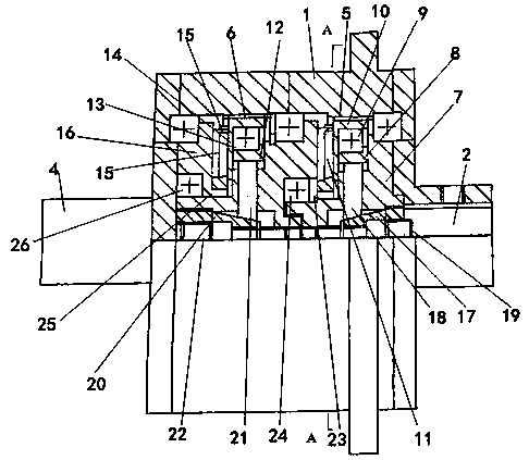
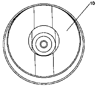
The invention discloses a two-stage speed reducer with a small tooth difference. The two-stage speed reducer with the small tooth difference comprises a shell, an input shaft, an intermediate shaft and an output shaft. A first connecting sleeve is connected to the input shaft, a first bearing inner sleeve is arranged on the first connecting sleeve, a first outer gear is installed on the first bearing inner sleeve through a first bearing and meshes with a first inner gear ring, and a first radial clearance adjusting device is arranged on the input shaft. The intermediate shaft is arranged on the input shaft in a sleeving mode, the first outer gear is connected with the intermediate shaft through a first cross connecting disc, a second bearing inner sleeve is arranged on the intermediate shaft, a second outer gear is installed on the second bearing inner sleeve through a second bearing and meshes with a second inner gear ring, and a second radial clearance adjusting device is arranged onthe input shaft. The output shaft stretches out of the end, opposite to the input shaft, of the shell, the second outer gear is connected with a second connecting sleeve through a second cross connecting disc, and the second connecting sleeve is fixedly connected with the output shaft and arranged on the intermediate shaft in a sleeving mode. The two-stage speed reducer with the small tooth difference is high in transmission accuracy and large in transmission ratio.

Description

technical field [0001] The invention belongs to the technical field of reducers, in particular to a two-stage reducer with a small tooth difference. Background technique [0002] For occasions with large transmission ratio requirements for high-speed input and ultra-low-speed output, harmonic reducers or RV reducers are often used. However, the harmonic reducer is difficult to manufacture, the flexible spline material requirements are extremely high, the flexible spline is fragile, and the cost of the special bearing is high. The RV reducer also has the problems of manufacturing difficulty and high manufacturing cost. The small tooth difference reducer is equipped with a small tooth difference planetary gear transmission, which is a planetary gear transmission composed of a pair of internal meshing gears with a small difference in the number of teeth and an output mechanism. It has a large transmission ratio, simple structure and low manufacturing cost. Advantages, but the ...

Claims


Application Information

Patent Timeline
Patent Type & Authority Applications(China)
IPC IPC(8): F16H1/32F16H57/023F16H57/08F16H57/12
CPCF16H1/32F16H57/023F16H57/08F16H57/12F16H2057/02086
Inventor 寇君洲
Owner 天津德恒源科技有限公司
Learn More