
Parallel battery management system

A battery management system and battery management technology, applied in battery circuit devices, current collectors, electric vehicles, etc., can solve problems such as excessive current, component damage, and excessive voltage difference

Active Publication Date: 2020-01-17
CELXPERT ENERGY CORP
View PDF5 Cites 1 Cited by
  • Summary
  • Abstract
  • Description
  • Claims
  • Application Information

AI Technical Summary

Problems solved by technology

[0004] However, in the existing parallel battery modules, when multiple battery modules are connected in parallel, according to the electrical characteristics, the current will flow from the battery module with higher voltage to the battery module with lower voltage. If the voltage difference between multiple battery modules If it is too large, not only will it generate too much current, but it will even generate sparks, which may damage the components or cause an explosion. Therefore, a management mechanism is urgently needed to control the time point when multiple battery modules are connected in parallel.

Method used


Image

  • Parallel battery management system
  • Parallel battery management system
  • Parallel battery management system

Examples


no. 1 example

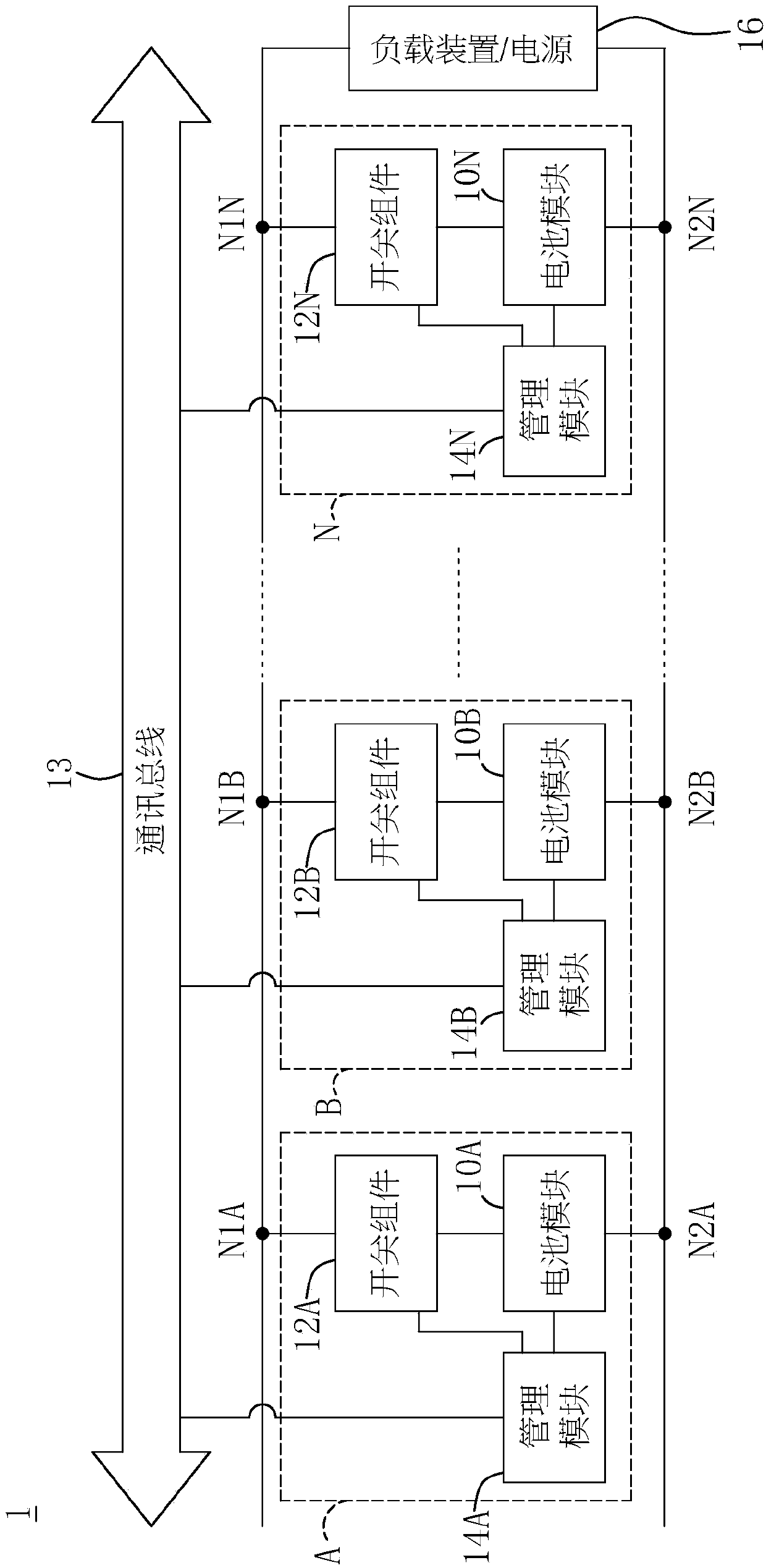
[0030] see figure 1 as shown, figure 1 It is a block diagram of the parallel battery management system according to the first embodiment of the present invention. As shown in the figure, the parallel battery management system 1 includes a plurality of battery blocks A, B, ..., N connected in parallel with each other and a communication bus 13, and the multiple battery blocks A, B, ..., N and the load device / power supply 16 connected in parallel. The battery blocks A, B, . . . , N respectively include switch assemblies 12A, 12B, . The battery modules 10A, 10B, . . . , 10N are connected in series with the switch assemblies 12A, 12B, . . . , 12N, respectively.

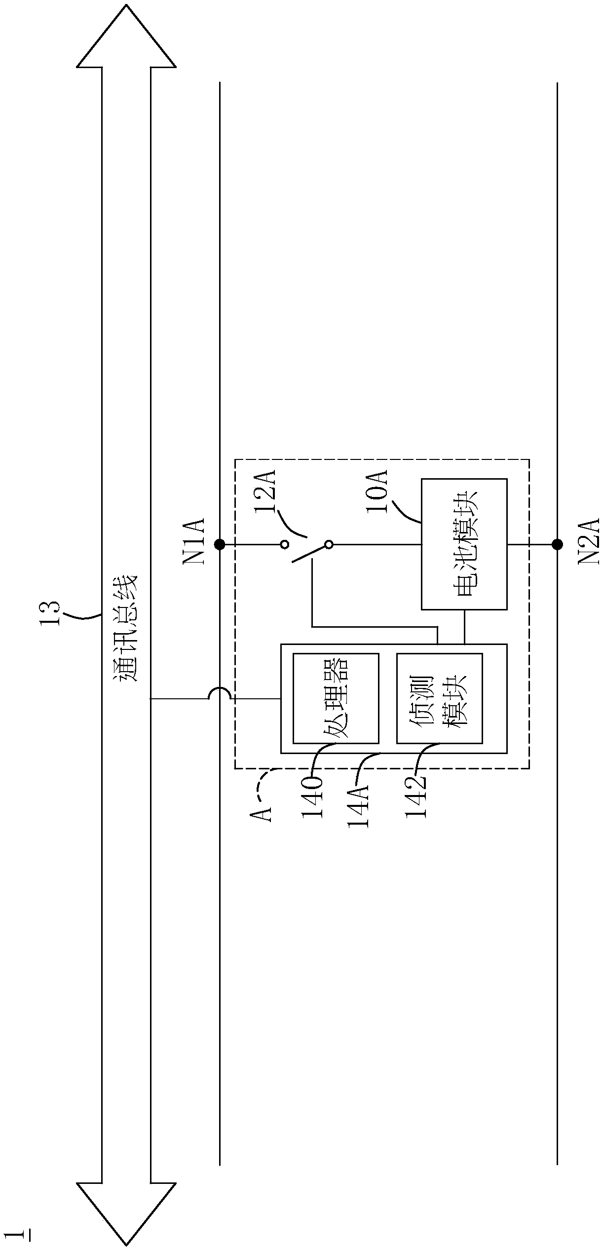
[0031] see further figure 2, which is an enlarged view of the battery block A of the parallel battery management system according to the first embodiment of the present invention. Taking the battery block A as an example, the battery block A includes a switch assembly 12A, a battery module 10A and a management modul...

no. 2 example

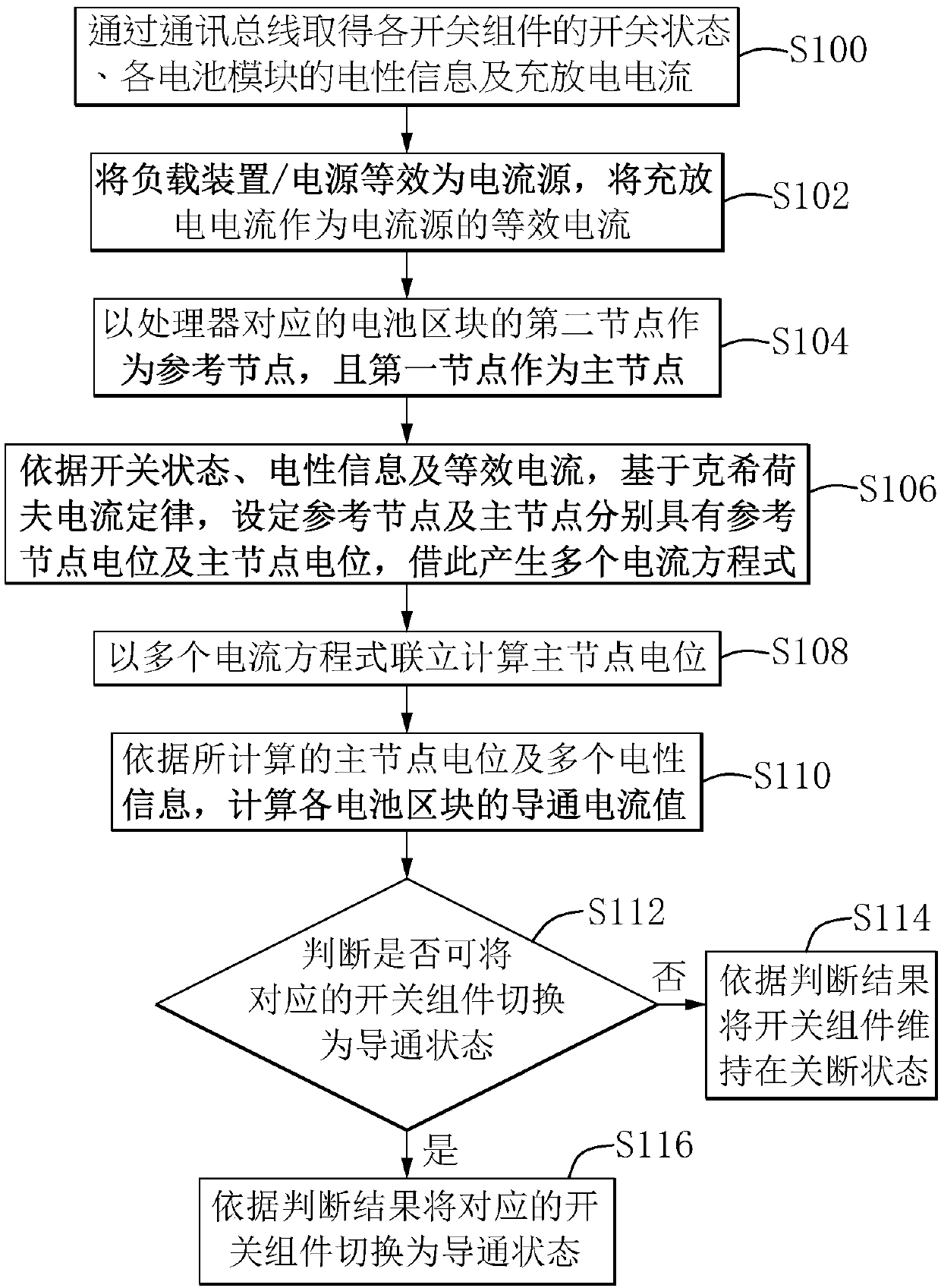
[0039] Please refer to image 3 , is a flow chart of the management program of the parallel battery management system in the second embodiment of the present invention, and the process provided in this embodiment can be referred to together figure 1 and figure 2 . As shown, the hypervisor consists of the following steps:

[0040] Step S100 : Obtain the switch state of each switch assembly 12A, 12B, . . . , 12N, the electrical information of each battery module 10A, 10B, . Each battery module 10A, 10B, . . . , 10N may include a battery source and an internal resistance of the battery, so the electrical property information may include the open circuit voltage of the battery source and the internal resistance of the battery.

[0041] Step S102: The load device / power source 16 is equivalent to a current source, and the charging and discharging current is used as an equivalent current of the current source. In addition, the processor 140 can be further configured to store eac...

no. 3 example

[0053] will now refer to Figure 4 An example of the operation of the parallel battery management system of the present invention is described. Figure 4 It is a circuit layout diagram of an operation example of the parallel battery management system according to the third embodiment of the present invention.

[0054] Such as Figure 4 As shown, a simplified circuit diagram of a parallel battery management system 2 is provided. The parallel battery management system 2 includes battery blocks A, B, and C. The battery blocks A, B, and C are connected in parallel with the power supply, and each includes switch assemblies 12A, 12B, and 12C and battery modules 10A, 10B, and 10C. In this situation, the switch components 12A, 12B are already in the conducting state, but the switch component 12C is not yet conducting, and the battery modules 10A, 10B, 10C each include internal resistors R1, R2, R3 and voltage sources S1, S2, S3 , wherein, the resistance value of the internal resist...


PUM


Abstract

The invention discloses a parallel battery management system and method. The system comprises a plurality of battery blocks connected in parallel, a load device / power supply and a communication bus. Each battery block comprises a switch assembly, a battery module and a management module, the management module comprises a processor and a detection module, and the detection module is used for detecting the electrical information of the battery module, the on-off state of the switch assembly and the charging and discharging current of the load device / power supply. The processor is configured to execute a management program, generate a plurality of current equations based on a Kirchhoff current law, at the same time, calculate the potential of a main node, and calculate the conduction currentvalue of each battery block after the switch assemblies are switched into the conduction state, and judge whether the corresponding switch assemblies can be switched into the conduction state or not according to a preset current threshold value and the conduction current values, and generate a judgment result, so that the parallel connection time point of the battery modules can be accurately andproperly controlled.

Description

technical field [0001] The invention relates to a parallel battery management system and method, in particular to a parallel battery management system and method for battery management based on a node method. Background technique [0002] The development of high-power battery packs is rapid, but the weight and safety of batteries make the transportation problem very restricted. [0003] If the low-power battery modules can be combined into a high-power battery module according to the application, coupled with ideal parallel management, the transportation problem can be alleviated, and various market demands can be met. [0004] However, in the existing parallel battery modules, when multiple battery modules are connected in parallel, according to the electrical characteristics, the current will flow from the battery module with higher voltage to the battery module with lower voltage. If the voltage difference between multiple battery modules If it is too large, it will not ...

Claims


Application Information

Patent Timeline
Patent Type & Authority Applications(China)
IPC IPC(8): H02J7/00
CPCY02E60/10
Inventor 李成泰陈韦匡谢宏伟
Owner CELXPERT ENERGY CORP
Learn More