
Structure and method for measuring precision of high-speed comparator based on TDC chip

A high-speed comparator and chip technology, applied in the direction of pulse processing, electrical components, pulse technology, etc., can solve the problems of unable to automate testing, batch automation, and high frequency requirements of input signals, so that it is not easy to trigger false trigger comparison, realize accuracy, and measure high resolution effects

Active Publication Date: 2020-01-17
SHANGHAI NCATEST TECH CO LTD
View PDF8 Cites 4 Cited by
  • Summary
  • Abstract
  • Description
  • Claims
  • Application Information

AI Technical Summary

Problems solved by technology

[0024] i. Cannot be automated in batches
[0025] It requires manual operation by the tester, cannot automate the test, and will introduce additional errors due to the different operation methods of the tester;
[0026] ii. High requirements on input signal frequency

Method used


Image

  • Structure and method for measuring precision of high-speed comparator based on TDC chip
  • Structure and method for measuring precision of high-speed comparator based on TDC chip
  • Structure and method for measuring precision of high-speed comparator based on TDC chip

Examples


Embodiment Construction

[0074] Attached below Figure 4-6 , the specific embodiment of the present invention will be further described in detail.

[0075] see Figure 4 , Figure 4 It is a block schematic diagram of a preferred embodiment of the structure of the present invention based on the TDC (Time-Digital Converter) chip to measure the precision of the high-speed comparator. As shown in the figure, in addition to the high-speed comparator to be tested, the structure may include a signal generation module, a control module and a TDC chip module; wherein, the signal generation module generates a set of N pulse signals, square wave signals or sawtooth wave signals, In some other embodiments of the present invention, the signal generator can generate a group of N pulse signals, square wave signals or sawtooth wave signals under the control of the control module; wherein, N is a positive integer greater than or equal to 2.

[0076] The same as the voltage test method in the prior art, the positive...


PUM


Abstract

The invention discloses a structure and method for measuring the precision of a high-speed comparator based on a TDC chip. The structure comprises a signal generation module, a control module and a TDC chip module, wherein one input end of the high-speed comparator receives direct-current threshold voltage, the other input end of the high-speed comparator receives a group of periodic signals output by the signal generation module, and the TDC chip module comprises an input unit, a plurality of first measurement channels, a plurality of second measurement channels, a processing unit and an output unit; and the delay error calculation unit is used for calculating delay errors of input and output signals of the high-speed comparator in each period of the internal reference clocks and / or calculating period errors of the high-speed comparator in two adjacent internal reference clock periods, and outputting test results of the delay errors and the period errors of the high-speed comparator.

Description

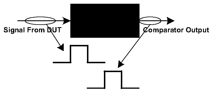
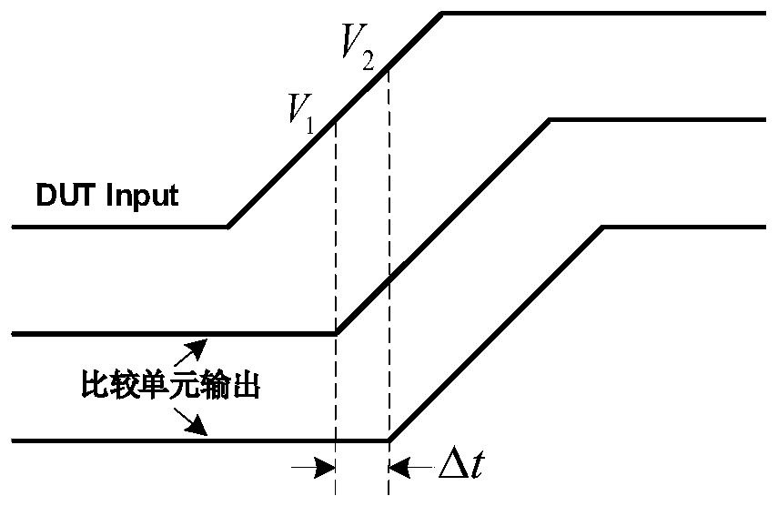
technical field [0001] The invention relates to the field of semiconductor automatic testing equipment, in particular to a structure and method for measuring the precision of a high-speed comparator. Background technique [0002] A comparator is an electronic component that outputs different voltage results at the output terminal by comparing the magnitude of the current or voltage at the two input terminals. see figure 1 , figure 1 The schematic diagram of the input and output error generation principle of the high-speed comparator shown. As shown in the figure, the main function of the high-speed comparator is to quickly compare the input signals, and then output the comparison result. In the field of ATE (semiconductor automated test equipment), high-speed comparators are often integrated inside the PE chip (Pin Electronics) to capture the signal waveform sent by DUT (Device Under Test) to ATE (semiconductor automated test equipment), which is a signal timing analysis ...

Claims


Application Information

Patent Timeline
Patent Type & Authority Applications(China)
IPC IPC(8): H03K5/24H03K5/00
CPCH03K5/24H03K5/00H03K2005/00084Y02D10/00
Inventor 徐波波
Owner SHANGHAI NCATEST TECH CO LTD
Learn More