
Manure scraper for breeding plant

A technology for aquaculture plants and manure machines, which is applied in the field of aquaculture equipment, can solve the problems of poor wear resistance of walking wheels, increased traction resistance, and short service life, and achieves the effects of low cost, stable friction and easy operation.

Inactive Publication Date: 2020-01-21
CHONGQING UNIV OF ARTS & SCI
View PDF1 Cites 0 Cited by
  • Summary
  • Abstract
  • Description
  • Claims
  • Application Information

AI Technical Summary

Problems solved by technology

[0002] As we all know, the manure scraper system is composed of a manure scraper pulled by a wire rope and a concrete dung ditch matched with it. The dung scraper reciprocates in the ditch to clean up the dung. The Chinese invention patent CN204443537U discloses A track guide wheel mechanism for a step-by-step manure scraper, including a U-shaped bracket and a guide wheel fixed on the U-shaped bracket. The guide wheel is rotatably fixed on the two side walls of the U-shaped bracket. When the guide rail is working, the fork on the machine head will not collide with the shaft of the guide wheel, thus overcoming the problem of jamming the machine. The existing track-type manure scraper system generally installs a walking wheel at the bottom of the manure scraper. The manure scraper is supported by the walking wheels, but the wear resistance of the walking wheels is poor, and the manure scraper generally works 24 hours. With the wear of the walking wheels, it will increase the distance between the manure scraping trolley and the manure ditch. Friction increases the invalid traction resistance, the service life is short, the follow-up maintenance cost is high, and it is easy to appear horizontal, tail lifting and stuck during the operation of the manure scraper, resulting in low reliability

Method used


Image

  • Manure scraper for breeding plant
  • Manure scraper for breeding plant
  • Manure scraper for breeding plant

Examples


Embodiment Construction

[0021] The following will clearly and completely describe the technical solutions in the embodiments of the present invention with reference to the accompanying drawings in the embodiments of the present invention. Obviously, the described embodiments are only some, not all, embodiments of the present invention.

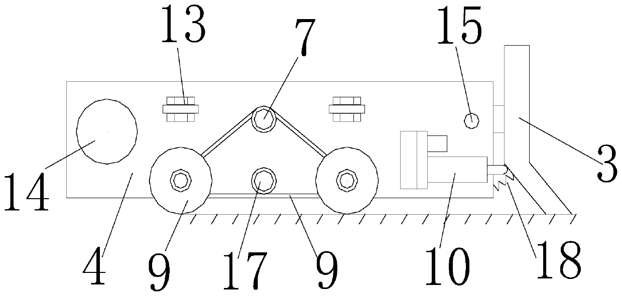
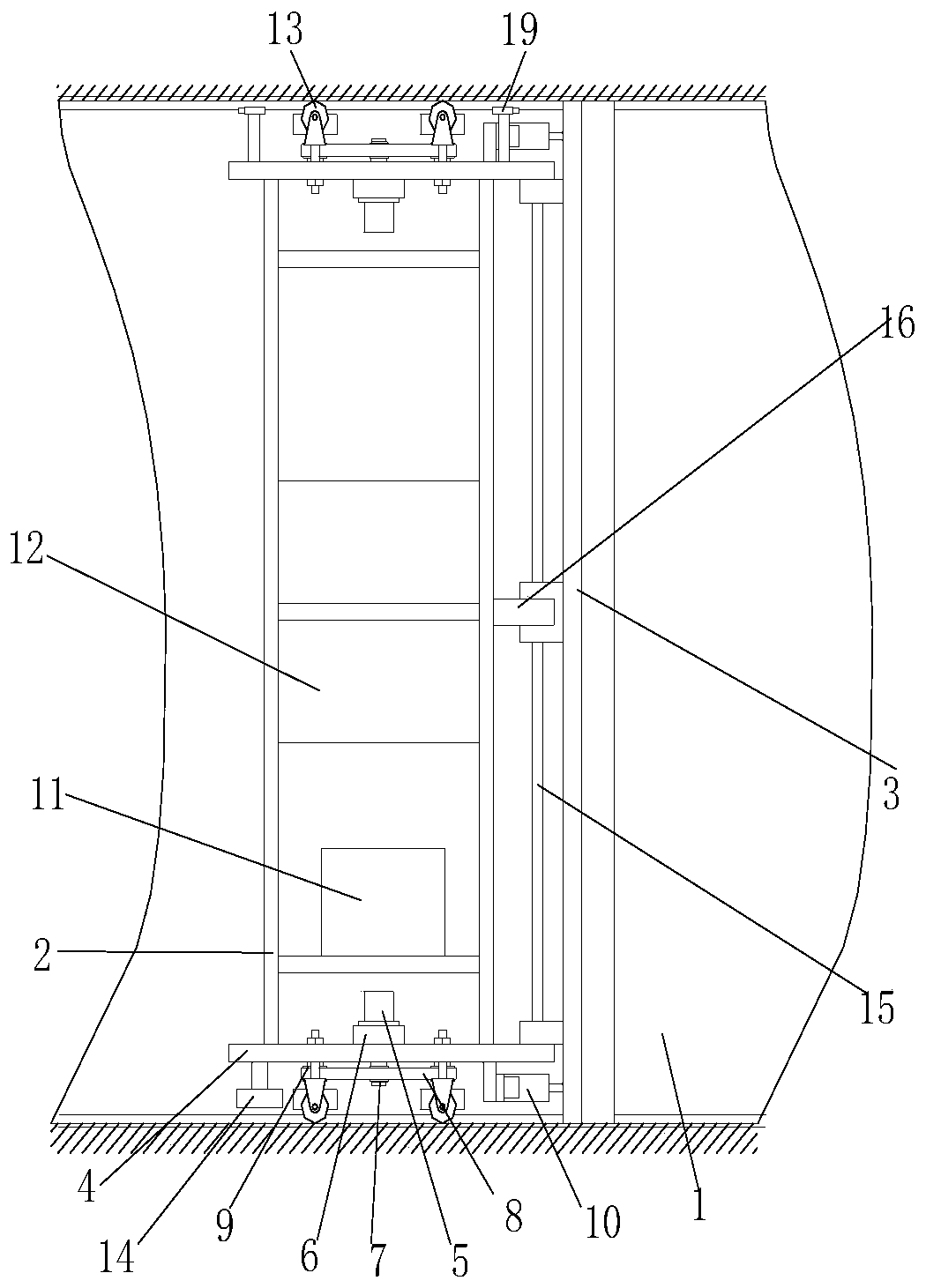
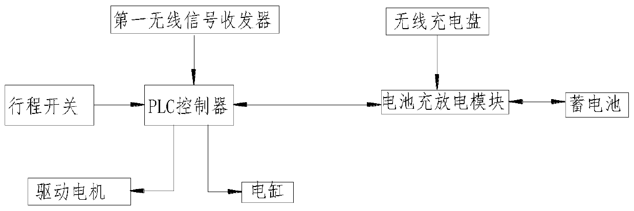
[0022] Figure 1-3 It is a structural schematic diagram of the present invention, a manure scraper for a breeding plant, including a manure collection tank, a frame arranged in the manure collection tank and a manure scraping push plate horizontally arranged in the manure collection tank, the manure scraper One side of the push plate is hingedly connected with the frame, and the lower part of the other side is provided with an arc-shaped plate that is in contact with the bottom of the manure collection tank for scraping manure. The inner wall of the side plate is provided with a synchronous motor, and the outer wall of the side plate is provided with a pair of horizo...


PUM


Abstract

The invention discloses a manure scraper for a breeding plant. The manure scraper comprises a manure collecting tank, a frame arranged in the manure collecting tank, and a manure scraping push plate horizontally arranged in the manure collecting tank. One side of the manure scraping push plate is hinged to the frame, and an arc-shaped plate, which contacts the bottom of the manure collecting tankand is used for scraping manure, is arranged on the lower portion of the other side of the manure scraping push plate. Side plates are arranged at two ends, close to the edge of the manure collectingtank, of the frame respectively. A synchronous motor is arranged on the inner wall of each side plate. A pair of horizontal travelling wheels and a driving wheel are arranged on the outer wall of eachside plate. The driving wheels are located between the travelling wheels and connected with the synchronous motors. The travelling wheels in pair and the corresponding driving wheel are in triangulararrangement, and transmission belts are arranged between the driving wheels and the travelling wheels. The manure scraper has the advantages that the synchronous motors and the travelling wheels in pair are arranged on the two side plates of the frame, the synchronous motors drive the driving wheels to rotate, transmission between the driving wheels and the travelling wheels is achieved through the transmission belts to enable the frame to move back and forth along the manure collecting tank, and the manure scraping push plate is pushed to scrape manure; the manure scraper is simple in structure, convenient to operate and low in cost.

Description

technical field [0001] The invention relates to the technical field of breeding equipment, in particular to a manure scraper for breeding plants. Background technique [0002] As we all know, the manure scraper system is composed of a manure scraper pulled by a wire rope and a concrete dung ditch matched with it. The dung scraper reciprocates in the ditch to clean up the dung. The Chinese invention patent CN204443537U discloses A track guide wheel mechanism for a step-by-step manure scraper, including a U-shaped bracket and a guide wheel fixed on the U-shaped bracket. The guide wheel is rotatably fixed on the two side walls of the U-shaped bracket. When the guide rail is working, the fork on the machine head will not collide with the shaft of the guide wheel, thus overcoming the problem of jamming the machine. The existing track-type manure scraper system generally installs a walking wheel at the bottom of the manure scraper. The manure scraper is supported by the walking w...

Claims


Application Information

Patent Timeline
Patent Type & Authority Applications(China)
IPC IPC(8): A01K1/01A01K31/04
CPCA01K1/0132A01K31/04
Inventor 唐大勇
Owner CHONGQING UNIV OF ARTS & SCI
Learn More