
Cleaning device and method for two-loop valve cages

A cleaning device and a secondary circuit technology, applied in the coating process of metal materials, etc., can solve problems such as inability to descale, inability to remove, and little effect, and achieve the effect of accelerating efficiency

Pending Publication Date: 2020-01-21
CNNC NUCLEAR POWER OPERATION MANAGEMENT +1
View PDF6 Cites 0 Cited by
  • Summary
  • Abstract
  • Description
  • Claims
  • Application Information

AI Technical Summary

Problems solved by technology

Since the opening diameter of the small hole in the cage of the main feedwater regulating valve is only about 6mm (millimeters), it cannot be descaled by general mechanical cleaning methods. The cage is cleaned by the usual high-pressure water gun and ultrasonic method, although there is a little scale Loose, but still deposited in the pores, with little effect and cannot be removed

Method used


Image

  • Cleaning device and method for two-loop valve cages
  • Cleaning device and method for two-loop valve cages

Examples


Embodiment Construction

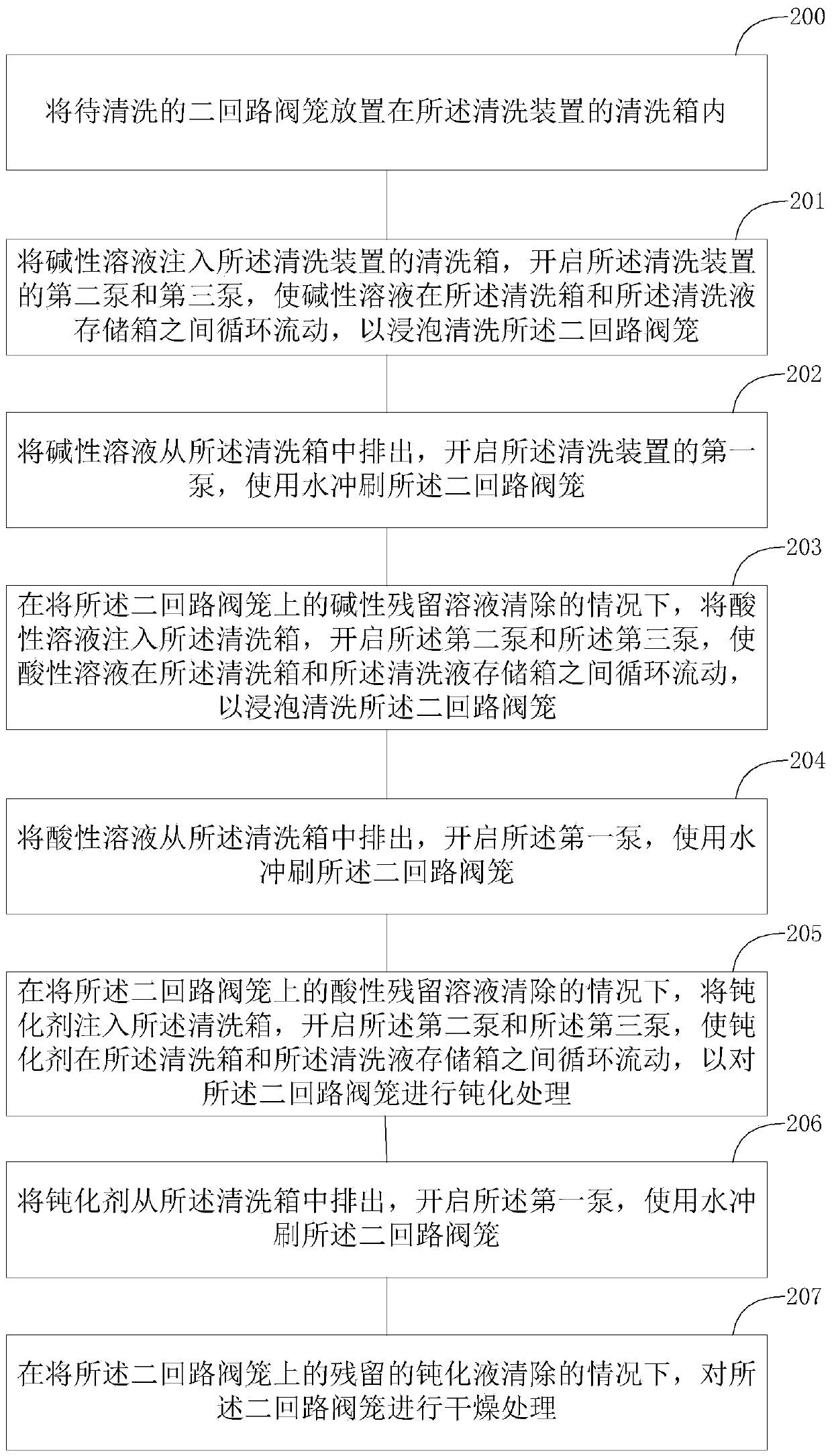
[0043] The present invention will be described in further detail below in conjunction with the accompanying drawings and specific embodiments.

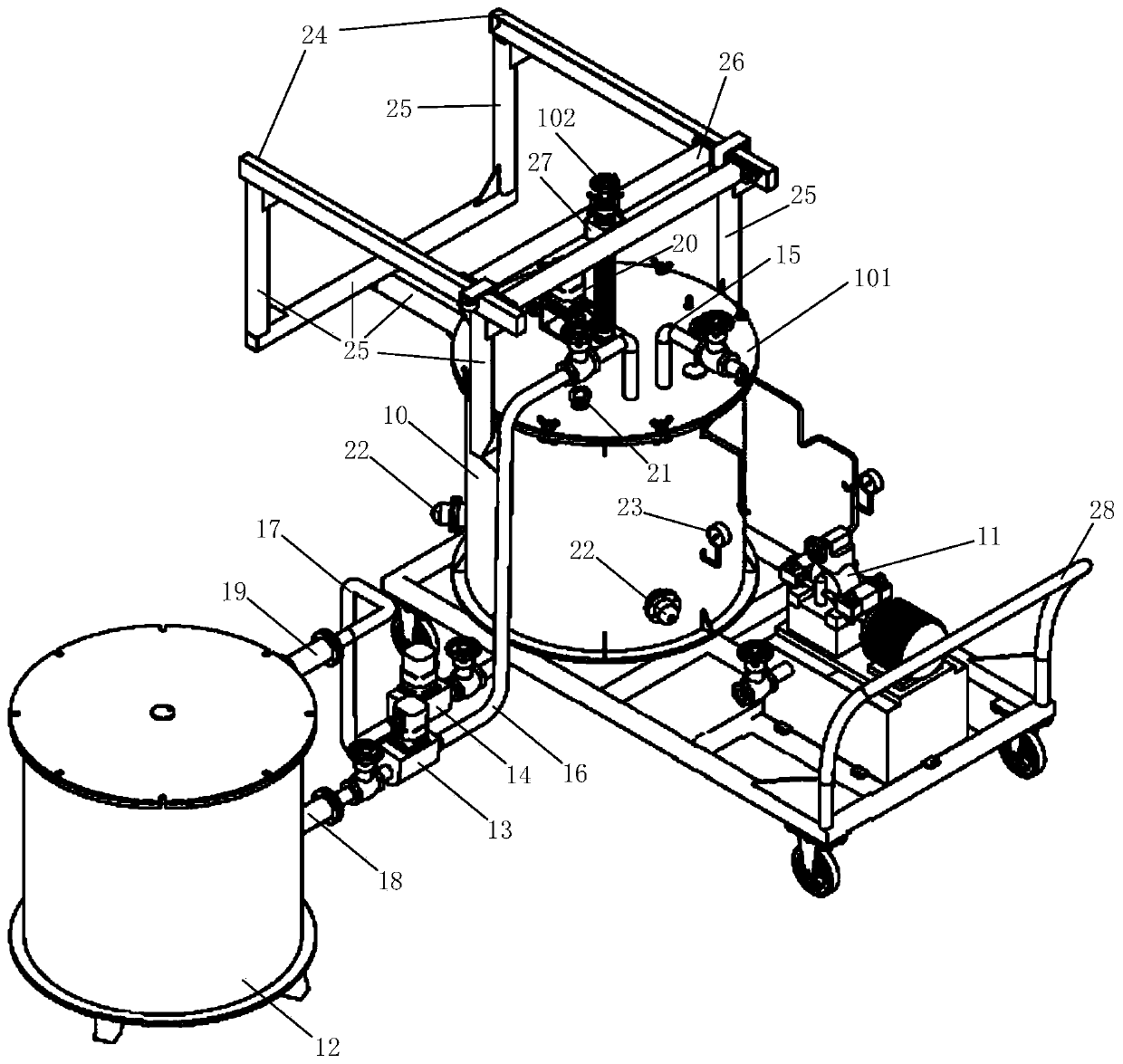
[0044] figure 1 It is a schematic diagram of a cleaning device for a secondary circuit valve cage shown according to an exemplary embodiment. Such as figure 1 As shown, the cleaning device for the secondary circuit valve cage may include: a cleaning tank 10, a first pump 11, a cleaning liquid storage tank 12, a second pump 13, a third pump 14, a water inlet pipe 15, and a cleaning liquid filling pipe 16. Cleaning liquid recovery pipe 17; the cleaning tank 10 is used to accommodate the secondary circuit valve cage to be cleaned; the first pump 11 is a high-pressure water pump, the first pump 11 is connected to a water source, and the cleaning tank 10 is connected to a water source A water inlet pipe 15 is connected between the first pumps 11, and the first pump 11 can pump water from a water source into the cleaning tank 10 through t...


PUM


Abstract

The invention belongs to the technical field of nuclear power maintenance, and in particular, relates to a cleaning device and method for two-loop valve cages. The cleaning device for the two-loop valve cages comprises a cleaning tank, a first pump, a cleaning liquid storage box, a second pump, a third pump, a water inlet pipe, a cleaning liquid injecting pipe and a cleaning liquid recovery pipe;the cleaning tank is used for accommodating two-loop valve cages to be cleaned; the first pump is a high-pressure pump, and can pump water of water sources into the cleaning tank through the water inlet pipe to scour the two-loop valve cages; the cleaning liquid injecting pipe and the cleaning liquid recovery pipe are connected between the cleaning liquid storage box and the cleaning tank; the second pump is connected to the cleaning liquid injecting pipe for pumping cleaning liquid in the cleaning liquid storage box into the cleaning tank through the cleaning liquid injecting pipe; and the third pump is connected to the cleaning liquid recovery pipe, and is used for pumping the cleaning liquid in the cleaning tank into the cleaning liquid storage box through the cleaning liquid recovery pipe. The cleaning device can improve the cleaning efficiency of the two-loop valve cages.

Description

technical field [0001] The invention belongs to the technical field of nuclear power maintenance, and in particular relates to a cleaning device and method for a valve cage of a secondary circuit. Background technique [0002] Since the 3rd fuel cycle operation of Fangjiashan Unit 2#, the valve openings of the three main feedwater regulating valves (models 2ARE031VL / 032VL / 033VL) of the main feedwater ARE (main feedwater flow control system) have a tendency to increase abnormally, from 52% Slowly increases to a maximum close to 70%. The main feed water regulating valve is an important equipment of the secondary circuit system of the nuclear power plant. The valve opening limit is required to be 70% during the normal operation of the system. If the valve opening continues to increase, it will seriously affect the safe operation of the unit. [0003] The maintenance personnel dismantled and overhauled the main feedwater regulating valve 2ARE032VL with the largest opening, and ...

Claims


Application Information

Patent Timeline
IPC IPC(8): C23G3/00C23G1/14C23G1/02C23C22/73
CPCC23G3/00C23G1/14C23G1/02C23C22/73
Inventor 王安宁张铭刻翁云峰王成林胡跃华费志松孙勤王今芳沈君庄佳翔蒋开川汤昊刘强司先国郭鹏飞顾为柏
Owner CNNC NUCLEAR POWER OPERATION MANAGEMENT
Learn More