Gate groove bottom silt-prevention elastic sill and silt-prevention method

A gate slot and anti-silting technology, which is applied in the direction of barrage/weir, water conservancy engineering, marine engineering, etc., can solve the problems of increasing operating cost, difficulty in cobblestones, labor, etc., and achieve lower operating costs, good application prospects, and long service life. Effect

Pending Publication Date: 2020-01-21
POWERCHINA XIBEI ENG
View PDF0 Cites 0 Cited by
  • Summary
  • Abstract
  • Description
  • Claims
  • Application Information

AI Technical Summary

Problems solved by technology

[0003] The purpose of the present invention is to overcome the deficiencies of the above-mentioned prior art, and provide an anti-silting elastic sill and anti-silting method at the bottom of the gate groove, which overcomes 1 in the prior art: it is very difficult to clean the bottom of the gate groove underwater or pebbles, often It is necessary to invite professional cleaning company divers to clean up; 2: Time-consuming and laborious, which increases operating costs; 3: There is no anti-silting equipment at the bottom of the gate slot in the prior art.

Method used


Image

  • Gate groove bottom silt-prevention elastic sill and silt-prevention method

Examples


specific Embodiment approach

[0023] It should be noted that the structures, proportions, sizes, etc. shown in this specification are only used to cooperate with the content disclosed in the specification for the understanding and reading of those familiar with this technology, and are not used to limit the conditions for the implementation of the present invention , any modification of structure, change of proportional relationship or adjustment of size shall still fall within the scope covered by the technical content disclosed in the present invention without affecting the effect and purpose of the present invention. .

[0024] At the same time, terms such as "upper", "lower", "left", "right", "middle" and "one" quoted in this specification are only for the convenience of description and are not used to limit this specification. The practicable scope of the invention and the change or adjustment of its relative relationship shall also be regarded as the practicable scope of the present invention without...

Embodiment 1

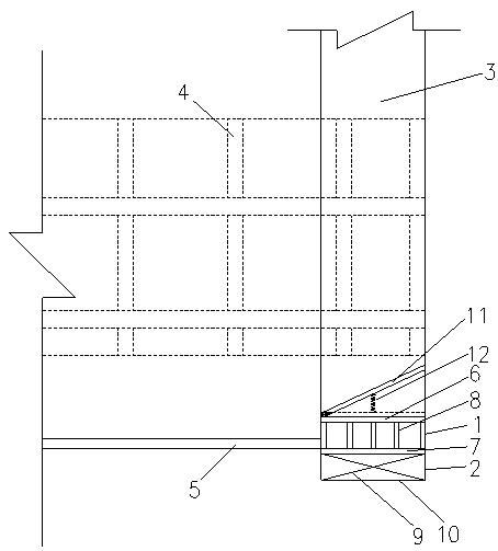
[0026] Such as figure 1 As shown, an anti-silting elastic bottom sill at the bottom of the gate groove is characterized in that it includes a bottom sill box 1, a spring seat 2 and an expansion plate assembly, wherein one side of the expansion plate assembly is tilted and rotatably fixed on the top of the bottom sill box 1, wherein The upper end of the spring seat 2 is fixed to the bottom of the sill box 1, and the lower end of the spring seat 2 is fixed to the bottom of the gate groove 3, wherein the sill box 1 is higher than the fixed sill 5 outside the gate groove 3 without being under the pressure of the gate 4 .

Embodiment 2

[0028] Such as figure 1 As shown, an anti-silting elastic bottom sill at the bottom of the gate groove is characterized in that it includes a bottom sill box 1, a spring seat 2 and an expansion plate assembly, wherein one side of the expansion plate assembly is tilted and rotatably fixed on the top of the bottom sill box 1, wherein The upper end of the spring seat 2 is fixed to the bottom of the sill box 1, and the lower end of the spring seat 2 is fixed to the bottom of the gate groove 3, wherein the sill box 1 is higher than the fixed sill 5 outside the gate groove 3 without being under the pressure of the gate 4 .

[0029] preferred, such as figure 1 As shown, the length and width of the sill box 1, the spring seat 2 and the telescopic plate assembly are respectively adapted to the length and width of the bottom of the gate groove 3, wherein the telescopic plate assembly is downward under the pressure of the gate 4 Rotate to be parallel to the bottom sill box 1, then the ...


PUM


Abstract

The invention discloses a gate groove bottom silt-prevention elastic sill and a silt-prevention method. The gate groove bottom silt-prevention elastic sill comprises sill box, a spring seat and a telescopic plate assembly, wherein one side of the telescopic plate assembly is inclinedly and rotatably fixed to the top part of the sill box; the upper end of the spring seat is fixed to the bottom partof the sill box; the lower end of the spring seat is fixed to the bottom part of a gate groove; and the sill box is higher than a fixed sill on the outer part of the gate groove under the circumstance that the sill box is not stressed by the pressure of a gate. According to the gate groove bottom silt-prevention elastic sill and the silt-prevention method provided by the invention, according to the own operation characteristics of the gate, sills at two ends of the gate groove are made into silt-prevention elastic sills, each silt-prevention elastic sill is formed by the sill box, the springseat and the telescopic plate assembly, the sill boxes are ejected for a certain height when the gate is started to rise, and the telescopic plate assemblies are ejected to form a certain angle with the sill boxes at the same time, so that the bottom silt or gravel is prevented from entering and staying on the sills of the gate groove.

Description

technical field [0001] The invention belongs to the technical field of water conservancy and hydropower, and in particular relates to an anti-silting elastic sill at the bottom of a gate groove and an anti-silting method. Background technique [0002] The bottom of the gate groove of the hydraulic structure is silted up or foreign matter such as pebbles enters, which directly affects the normal use of the gate. Since underwater cleaning is very difficult, it is often necessary to hire professional cleaning company divers to clean up, which is time-consuming and laborious, and increases operating costs. How to solve this problem has always been a topic of common concern in the industry. Contents of the invention [0003] The purpose of the present invention is to overcome the deficiencies of the above-mentioned prior art, and provide an anti-silting elastic sill and anti-silting method at the bottom of the gate groove, which overcomes 1 in the prior art: it is very difficul...

Claims


Application Information

Patent Timeline
Patent Type & Authority Applications(China)
IPC IPC(8): E02B8/02E02B7/26
CPCE02B7/26E02B8/02
Inventor 张春生朱增兵李岗赵清静
Owner POWERCHINA XIBEI ENG
Why Eureka
Try Eureka