
Sputtering tray and sputtering jigs

A tray and sputtering technology, which is applied in the field of sputtering, can solve problems such as uneven coating of products, and achieve the effects of easy handling, avoiding overflow plating, and uniform film thickness

Active Publication Date: 2020-01-24
UNIVERSAL SCIENTIFIC INDUSTRIAL (SHANGHAI) CO LTD
View PDF5 Cites 2 Cited by
  • Summary
  • Abstract
  • Description
  • Claims
  • Application Information

AI Technical Summary

Problems solved by technology

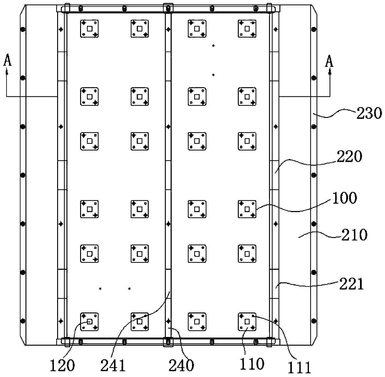
[0004] The present invention will solve the technical problem of uneven product coating in the prior art, and provide a sputtering tray and a sputtering fixture

Method used


Image

  • Sputtering tray and sputtering jigs
  • Sputtering tray and sputtering jigs
  • Sputtering tray and sputtering jigs

Examples


Embodiment Construction

[0036] In order to more clearly illustrate the embodiments of the present invention or the technical solutions in the prior art, the specific implementation manners of the present invention will be described below with reference to the accompanying drawings. Obviously, the accompanying drawings in the following description are only some embodiments of the present invention, and those skilled in the art can obtain other accompanying drawings based on these drawings and obtain other implementations.

[0037] In order to make the drawing concise, each drawing only schematically shows the parts related to the present invention, and they do not represent the actual structure of the product. In addition, to make the drawings concise and easy to understand, in some drawings, only one of the components having the same structure or function is schematically shown, or only one of them is marked. Herein, "a" not only means "only one", but also means "more than one".

[0038] In order t...


PUM


Abstract

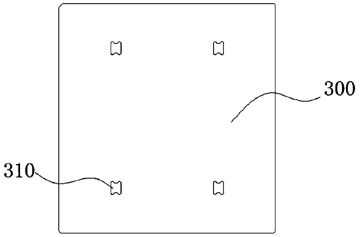
The invention provides a sputtering tray and sputtering jigs. The sputtering tray is positioned under target material in a sputtering chamber, and the jigs containing products to be sputtered are placed on the sputtering tray. The sputtering tray comprises a tray body and a plurality of supporting structures arranged on the tray body, wherein the supporting structures are provided with supportingsurfaces used for making the jigs placed on the supporting structures incline towards the central axis of the tray body, and the heights of the sides, away from the central axis, of the supporting surfaces are higher than the heights of the sides, close to the central axis, of the supporting surfaces, so that the contact probability of knocked target atoms with the side surfaces of the products, close to the edges of the tray body, on the jigs is increased, and the uniform film thicknesses of the sputtered products are ensured.

Description

technical field [0001] The invention relates to the field of sputtering, in particular to a sputtering tray and a sputtering fixture. Background technique [0002] Vacuum magnetron sputtering coating is a kind of physical vapor deposition. In physical vapor deposition, because different atoms have different incident angles and different velocities, as well as different velocity distributions and atomic concentration distributions, these determine the In , different molecules have different mean molecular free paths, so the thickness of atoms deposited on different positions of the substrate will have certain differences; [0003] Put the product on the jig of the magnetron sputtering machine for coating. After coating, the film thickness of the left and right sides of a single product varies greatly, so the film thickness of the product on the jig will be uneven. However, the large trays used in existing magnetron sputtering machines are also placed horizontally, and the ji...

Claims


Application Information

Patent Timeline
Patent Type & Authority Applications(China)
IPC IPC(8): C23C14/50C23C14/35
CPCC23C14/35C23C14/50
Inventor 周振国程金桥胡正华方宁王厦
Owner UNIVERSAL SCIENTIFIC INDUSTRIAL (SHANGHAI) CO LTD
Learn More