
Electric conduction brush used for solder stripping device and solder stripping device comprising electric conduction brush

A conductive brush and tin stripping technology, applied in the direction of electrolytic components, electrolysis process, etc., can solve the problems that tin is easily oxidized and tin stripping efficiency, PCB substrate is easily corroded, etc., so as to improve the tin stripping effect and speed up the tin stripping rate. , cost saving effect

Pending Publication Date: 2020-01-24
苏州金易得环保科技有限公司
View PDF6 Cites 2 Cited by
  • Summary
  • Abstract
  • Description
  • Claims
  • Application Information

AI Technical Summary

Problems solved by technology

However, in the above-mentioned tin stripping methods, there are often problems such as the substrate of the PCB is easily over-corroded, the tin is easily oxidized, and / or the efficiency of tin stripping is low.

Method used


Image

  • Electric conduction brush used for solder stripping device and solder stripping device comprising electric conduction brush
  • Electric conduction brush used for solder stripping device and solder stripping device comprising electric conduction brush
  • Electric conduction brush used for solder stripping device and solder stripping device comprising electric conduction brush

Examples


Embodiment Construction

[0023] The principle of the present invention will be further described in detail below in conjunction with the accompanying drawings and exemplary embodiments, so as to make the technical solution of the present invention clearer.

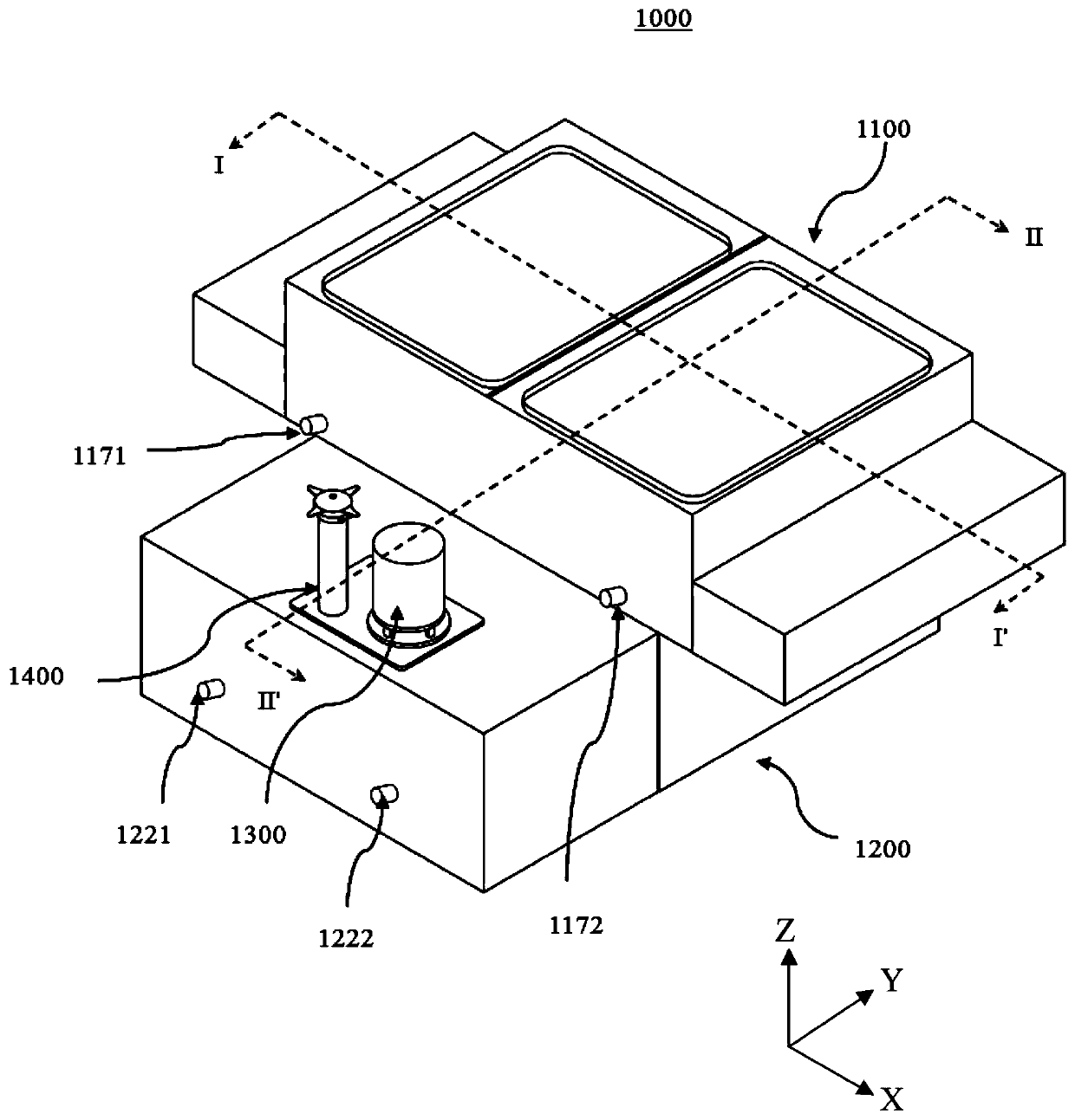
[0024] figure 1 is a perspective view of a desoldering device according to an exemplary embodiment of the present inventive concept. In the drawings, the X-axis, Y-axis and Z-axis are not limited to the three axes of the rectangular coordinate system and can be interpreted in a wider sense. For example, the X-axis, Y-axis, and Z-axis may be perpendicular to each other, or may represent different directions that are not perpendicular to each other.

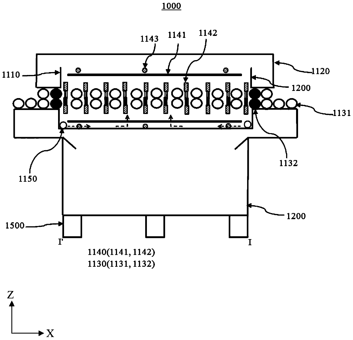
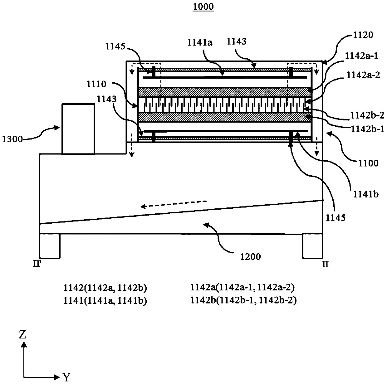
[0025] refer to figure 1 , The stripping equipment 1000 according to an exemplary embodiment of the present inventive concept may include a stripping tank assembly 1100 and a solution tank 1200 .

[0026] Such as figure 1 As shown in , the stripping tank assembly 1100 may at least partially overlap...


PUM


Abstract

The invention discloses an electric conduction brush used for a solder stripping device and the solder stripping device comprising the electric conduction brush. The solder stripping device can comprises a cathode plate and the electric conduction brush making contact with a PCB so as to apply voltage to the PCB in the solder stripping process. The electric conduction brush can comprise a brush handle electrically connected to an external power source, brush wires fixed and electrically connected to the brush handle, supporting parts which are overlapped with the brush wires and fixed to the brush handle together with the brush wires so as to support the brush wires, and a fixing part. The fixing part comprises a cover plate, and the cover plate covers part of the brush wires and part of the supporting parts and is combined to the brush handle so as to fix the brush wires and the supporting parts to the position between the brush handle and the fixing part. By the adoption of the solder stripping device comprising the electric conduction brush, the solder stripping rate can be increased, and the solder stripping effect is improved.

Description

technical field [0001] The invention relates to the technical field of metal plating stripping, in particular to a conductive brush used for tin stripping equipment and tin stripping equipment including the same. Background technique [0002] Printed Circuit Board (PCB) is one of the important parts of the electronics industry and is the support of electronic components. Usually, in the process of manufacturing printed circuit boards, after the circuit pattern is formed by screen printing or photochemical method, it is necessary to plate tin on the conductive pattern to form a corrosion-resistant metal protective layer to protect the circuit pattern, and then it can be used in subsequent alkali Protect the circuit pattern from being damaged by corrosion during the permanent etching process. After the alkaline etching is completed, the tin protective layer formed on the surface of the circuit pattern and the copper-tin alloy formed at the interface between the tin protective...

Claims


Application Information

Patent Timeline
Patent Type & Authority Applications(China)
IPC IPC(8): C25F5/00C25F7/00
CPCC25F5/00C25F7/00
Inventor 杨保严黄小露田宝龙王宗龙
Owner 苏州金易得环保科技有限公司
Learn More