Submerged floating tunnel shore connecting system, submerged floating tunnel, and submerged floating tunnel construction method

A technology for suspended tunnels and design methods, applied in pontoon bridges, artificial islands, water conservancy projects, etc., can solve problems such as affecting the structural safety, driving safety, passenger comfort experience, affecting the safety of suspended tunnels, and transmitting resonance risks. The effect of designing redundancy, improving safety and reliability, and reducing maintenance difficulty

Pending Publication Date: 2020-01-24
CHINA COMMUNICATIONS CONSTRUCTION
View PDF6 Cites 10 Cited by
  • Summary
  • Abstract
  • Description
  • Claims
  • Application Information

AI Technical Summary

Problems solved by technology

[0012] The purpose of the present invention is to overcome the problem that the existing floating tunnel research in the prior art still stays in the technical conception and test stage, and the technical conception of the buoy type floating tunnel has the problem that the horizontal stiffness is still weak, which affects the structural safety , driving safety and passenger comfort experience, the horizontal stiffness of the technical concept of the anchor-pull floating tunnel is still weak and it is also prone to elastic vibrations. The risk of resonance is large, which seriously affects the above-mentioned shortcomings of the safety of the floating tunnel, and a floating tunnel landing system and its floating tunnel are provided, and a construction method for the floating tunnel is also provided

Method used


Image

  • Submerged floating tunnel shore connecting system, submerged floating tunnel, and submerged floating tunnel construction method
  • Submerged floating tunnel shore connecting system, submerged floating tunnel, and submerged floating tunnel construction method
  • Submerged floating tunnel shore connecting system, submerged floating tunnel, and submerged floating tunnel construction method

Examples


Embodiment 1

[0107] Embodiment 1 provides a method for designing a floating tunnel, in which axial tension is applied to both ends of the tube body 1 of the floating tunnel. Of course, it is also possible to apply an axial pulling force along one end of the tube body 1 of the suspension tunnel, while the other end only provides a reaction force.

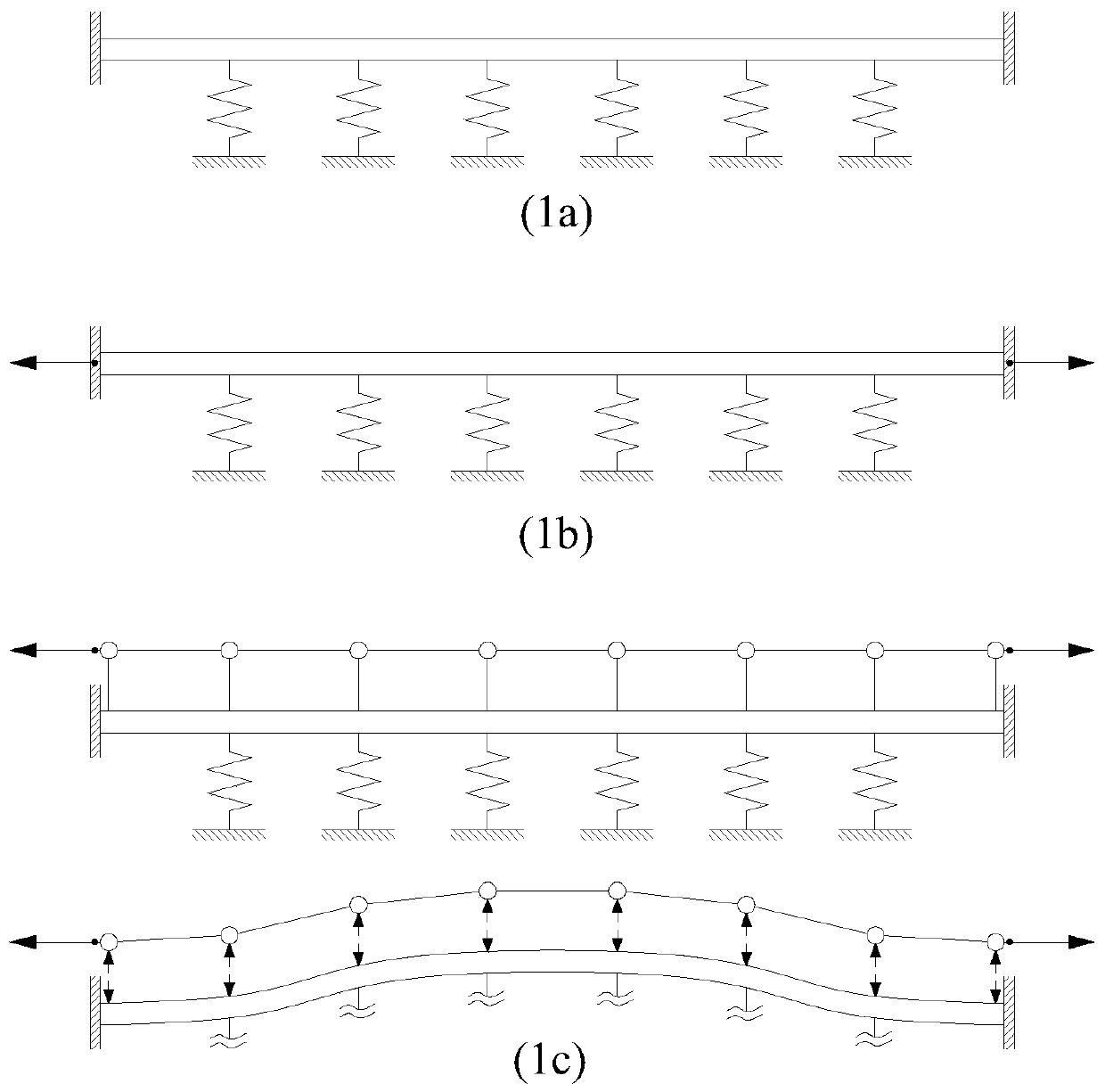
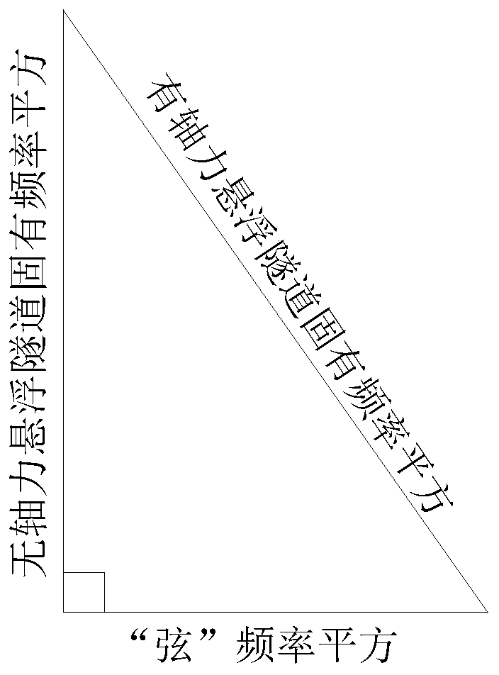
[0108] Through the force analysis of the suspension tunnel body 1, the change of front and rear force occurs when the both ends of the suspension tunnel body 1 are subjected to axial tension. Such as figure 1 As shown in a-1c, the structural stiffness system of the floating tunnel in the prior art is composed of the stiffness contributions of the pipe body 1 and the anchorage system (such as figure 1 As shown in a), the anchoring system can be a cable 22, a buoy, or both. In this embodiment, by applying the axial tension of the pipe body 1 ( figure 1 shown in b), which additionally increases the stiffness (see the principle figure 1 c), there...

Embodiment 2

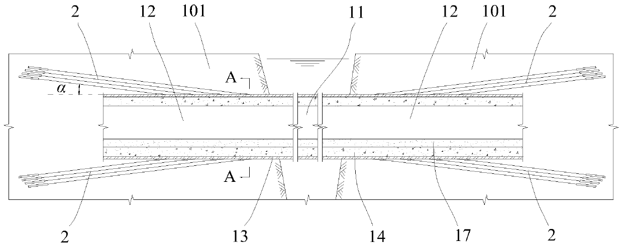
[0129] Such as Figure 3-5 As shown, this embodiment 2 also provides a floating tunnel landing system, including a joint section 12 located at the end of the floating tunnel, the joint section 12 can move axially along the pipe body, and the joint section 12 is provided with a tension device 2. The tension device 2 is used to apply axial tension to the joint section 12 .

[0130] Wherein, the above-mentioned joint section 12 passes through the shore foundation 101, and is not fixed or hingedly connected to the shore foundation 101. The joint section 12 can move along the axial direction of the pipe body 1 relative to the shore foundation 101, Avoiding the reaction force provided by the shore foundation 101 to the joint section 12 when the joint section 12 is pulled by the tension device 2 to reduce the influence of the horizontal stiffness of the tension device lifting the pipe body 1 .

[0131]The tension device 2 is connected to the shore foundation 101, and by directly con...

Embodiment 3

[0139] Such as Figure 3-5 As shown, this embodiment 3 provides a suspension tunnel, including a pipe body 1 and a hollow cavity 18, the pipe body 1 includes a suspension section 11, and the two ends of the suspension section 11 are respectively connected with Landing system: the joint sections 12 pass through the shore foundation 101 , and the two joint sections 12 are provided with tension devices 2 , and the tension devices 2 are used to apply axial tension to the corresponding joint sections 12 .

[0140] Wherein, the magnitudes of the above two axial pulling forces are the same, and the directions of the axial pulling forces are opposite. The suspension section 11 and the two joint sections 12 all include a steel plate layer 13 and a reinforced concrete layer 14 located in the steel plate layer 13, all the steel plate layers 13 are integral structural parts, and all the reinforced concrete layers 14 are integral structures pieces. The cross-sectional shape of the pipe b...


PUM


Abstract

The invention discloses a submerged floating tunnel shore connecting system, a submerged floating tunnel and a submerged floating tunnel construction method. A submerged floating tunnel design methodis characterized in that axial tension is correspondingly applied to one or both ends of a pipe body. The submerged floating tunnel shore connecting system comprises joint sections located at the endsof the pipe body, the joint sections can move in the axial direction, and tension devices for applying axial tension are connected to the joint sections; and the submerged floating tunnel comprises the pipe body and a hollow inner cavity, wherein the pipe body comprises a suspension section and a shore connecting system located at the two ends, and tension devices are arranged on the two joint sections. According to the design method and structure of the submerged floating tunnel, through applying the axial tension of the pipe body, the horizontal rigidity and the vertical rigidity of the whole pipe body can be remarkably increased, the self-vibration frequency of the pipe body structure is improved, and the safety and reliability of the submerged floating tunnel are improved; and it is conducive to the long-term use of a cable and a foundation anchored on a seabed or a river bed, the construction risk is lower, the manufacturing cost is lower, the construction cost is effectively saved, and the popularization is easy to implement.

Description

technical field [0001] The invention relates to the technical field of floating tunnel engineering, in particular to a floating tunnel landing system, the floating tunnel, and a construction method for the floating tunnel. Background technique [0002] As a new form of transportation through water, floating tunnels in water are conceived. Generally, the self-weight, buoyancy of the structure and the anchoring system installed on the underwater foundation work together to maintain the balance and stability of the floating tunnel in the water. Due to the complex structure and working environment of floating tunnels, there is no precedent for successful construction in the world. The technology of floating tunnels is still in the stage of technical conception and testing. [0003] The technical conception of the existing floating tunnel structure is generally divided into an anchor pull type and a buoy type. Among them, the structural buoyancy of the anchor-pull floating tunne...

Claims


Application Information

Patent Timeline
Patent Type & Authority Applications(China)
IPC IPC(8): E02D29/067
CPCE02D29/067E01D15/14E02D2250/00E02D2600/30
Inventor 林巍
Owner CHINA COMMUNICATIONS CONSTRUCTION
Why Eureka
Try Eureka