Pool wall prefabricated block splicing structure suitable for static pressure assembled pool and construction method thereof

A prefabricated block and prefabricated technology, applied in large-capacity bulk material storage, building types, buildings, etc., can solve the problems of easy bending of prefabricated block steel bars on the pool wall, so as to ensure the tensile and flexural properties and increase splicing Strength, the effect of ensuring the quality of the butt joint

Inactive Publication Date: 2020-01-24
HOHAI UNIV
View PDF6 Cites 2 Cited by
  • Summary
  • Abstract
  • Description
  • Claims
  • Application Information

AI Technical Summary

Problems solved by technology

[0005] Purpose of the invention: The first purpose of the present invention is to propose a pool wall prefabricated block splicing structure suitable for hydrostatic assembled pools, which solves the problems of splicing strength and anti-seepage of hydrostatic prefabricated pool prefabricated blocks under semi-concealed construction conditions , to solve the problems that the static pressure assembled pool needs to use the outer side of the pool to retain soil before the static pressure construction, and the exposed steel bars of the prefabricated block of the pool wall are easy to bend, etc.

Method used


Image

  • Pool wall prefabricated block splicing structure suitable for static pressure assembled pool and construction method thereof
  • Pool wall prefabricated block splicing structure suitable for static pressure assembled pool and construction method thereof
  • Pool wall prefabricated block splicing structure suitable for static pressure assembled pool and construction method thereof

Examples


Embodiment 1

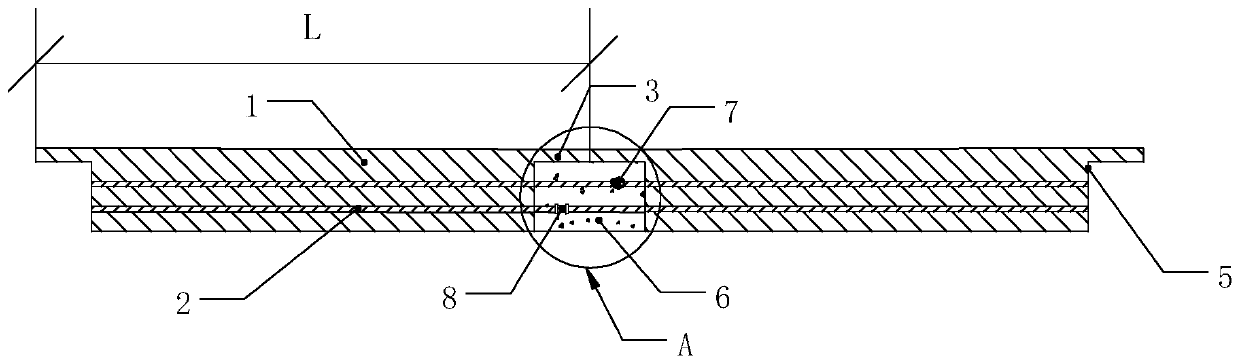
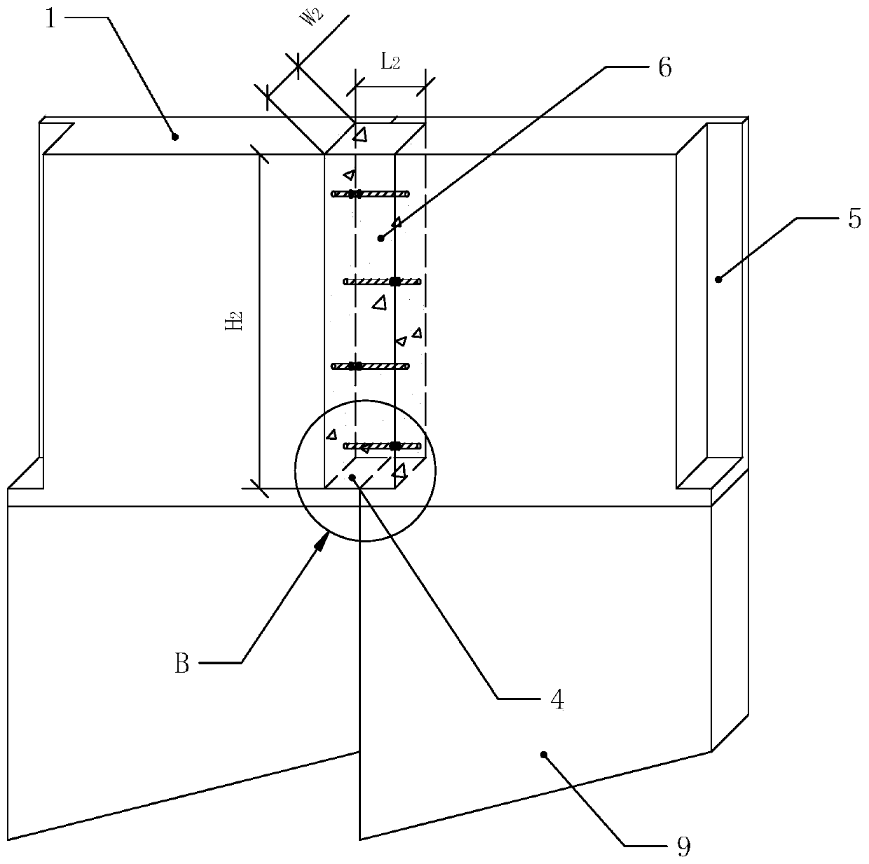
[0049] The length L1 of the static pressure assembled pool 10 is 6m, the width W1 is 6m, the height H1 is 2m, and the thickness T is 0.3m. The length L2 of the cast-in-place block 6 is 0.3m, the width W2 is 0.15m, the height H2 is 1.8m, and the length L of the cast-in-place block is 3m.

Embodiment 2

[0051] The length L1 of the static pressure assembled pool 10 is 8m, the width W1 is 8m, the height H1 is 2.5m, and the thickness T is 0.4m. The length L2 of the cast-in-place block 6 is 0.4m, the width W2 is 0.25m, the height H2 is 2.4m, and the length L of the prefabricated block is 3m.

Embodiment 3

[0053] The length L1 of the static pressure assembled pool 10 is 7m, the width W1 is 7m, the height H1 is 2m, and the thickness T is 0.35m. The length L2 of the cast-in-place block 6 is 0.35m, the width W2 is 0.2m, the height H2 is 1.9m, and the length L of the prefabricated block is 3m.


PUM


Abstract

The invention discloses a pool wall prefabricated block splicing structure suitable for a static pressure assembled pool and a construction method thereof. The splicing structure comprises a prefabricated block which is spliced along the circumferential direction to form a pool wall, a steel bar which penetrates through the prefabricated block and extends out from the circumferential end part of the prefabricated block, a splicing block which is positioned at the circumferential end part of the prefabricated block to form the outer wall of the pool and a soil retaining block which is positioned at the bottom of the prefabricated block, and the splicing block and the soil retaining block are enclosed to form a connecting groove for circumferential splicing, when the prefabricated blocks are assembled along the circumferential direction, two opposite steel bars in the connecting grooves of the adjacent prefabricated blocks are fixedly connected with each other, and concrete is filled inthe connecting grooves to form cast-in-place blocks. The construction method comprises the following steps of determining the size and the quantity of the prefabricated blocks according to the size of the water pool; manufacturing the prefabricated block, pressing the prefabricated block into a soil body, and butting the steel bars; pouring concrete to form the cast-in-place blocks. According tothe splicing structure and the construction method, the prefabricated block and the cast-in-place block are assembled to form the pool wall, and the prefabricated structure and the cast-in-place structure are combined, so that the anti-seepage performance of the pool wall is improved, and the integral rigidity of the structure is guaranteed.

Description

technical field [0001] The invention relates to a prefabricated pool structure, in particular to a pool wall prefabricated block splicing structure and construction method suitable for a static pressure assembled pool. Background technique [0002] Traditional prestressed concrete pools are divided into two types: circular and rectangular. The circular pool relies on high-strength steel wires to be wound and prestressed, and the rectangular pool uses four-corner cast-in-place concrete wall panels and prefabricated wall panels to ensure the integrity of the pool. Different from the traditional pool, the hydrostatic prefabricated pool is a pool built with static pressure technology. The hydrostatic assembly technology can greatly reduce the cost of foundation pit excavation and support, and at the same time increase the frictional resistance of the side wall of the pool to reduce the investment in anti-floating measures , but the existing supporting construction technology an...

Claims


Application Information

Patent Timeline
Patent Type & Authority Applications(China)
IPC IPC(8): E04H7/02E04H7/18
CPCE04H7/02E04H7/18
Inventor 王建孙淑华侯英伟张万年
Owner HOHAI UNIV
Why Eureka
Try Eureka