Propelling method for planar gliding of shield tunneling machine

A technology of shield machine and plane, which is applied in the direction of earth drilling, mining equipment, tunnels, etc., and can solve the problems of high consumption, low reuse rate, and high cost

Active Publication Date: 2020-01-24
HENAN POLYTECHNIC UNIV +1
View PDF11 Cites 0 Cited by
  • Summary
  • Abstract
  • Description
  • Claims
  • Application Information

AI Technical Summary

Problems solved by technology

The publication number is CN102337900A, which discloses a method for empty pushing of a circular matting shield machine. The device is provided with a bracket at the bottom of the shield machine, and two rows of vertical jacks are arranged on both sides, and the horizontal jack transmits force through the reaction device and the bracket. , the horizontal jack pushes the shield machine forward on the bracket, and then starts the vertical jack to lift the shield machine, the horizontal jack shrinks, pushes the bracket forward, shrinks th

Method used


Image

  • Propelling method for planar gliding of shield tunneling machine
  • Propelling method for planar gliding of shield tunneling machine
  • Propelling method for planar gliding of shield tunneling machine

Examples


Example Embodiment

[0060] Example 1

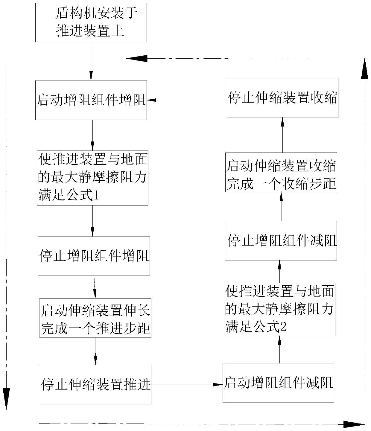
[0061] Such as figure 1 As shown, the present invention provides a plane sliding propulsion method of a shield machine, using such as Figure 2~8 The propelling device shown is realized; the propelling method is:

[0062] When the telescopic device 6 extends and advances, the resistance increasing component 4 is activated to increase the resistance, so that the acceleration of the shield machine 10 relative to the seat plate 2 is greater than the acceleration of the support frame 1 relative to the ground;

[0063] When the telescopic device 6 contracts, the resistance increasing assembly 4 is activated to reduce the resistance, so that the acceleration of the shield machine 10 relative to the seat plate 2 is smaller than the acceleration of the support frame 1 relative to the ground.

[0064] Specifically, the mass sum of the shield machine 10 and the telescopic device 6 is M d , The quality of support frame 1 is M zc , The quality of seat plate 2 is M zb , The mas...

Example Embodiment

[0078] Example 2

[0079] This embodiment also provides a plane sliding propulsion device of the shield machine, which can realize continuous propulsion and improve propulsion efficiency.

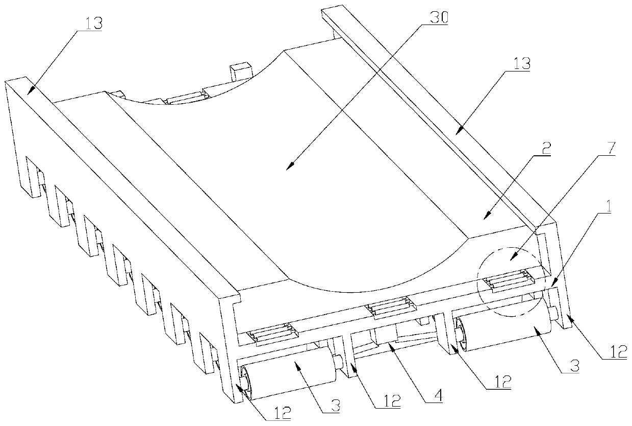
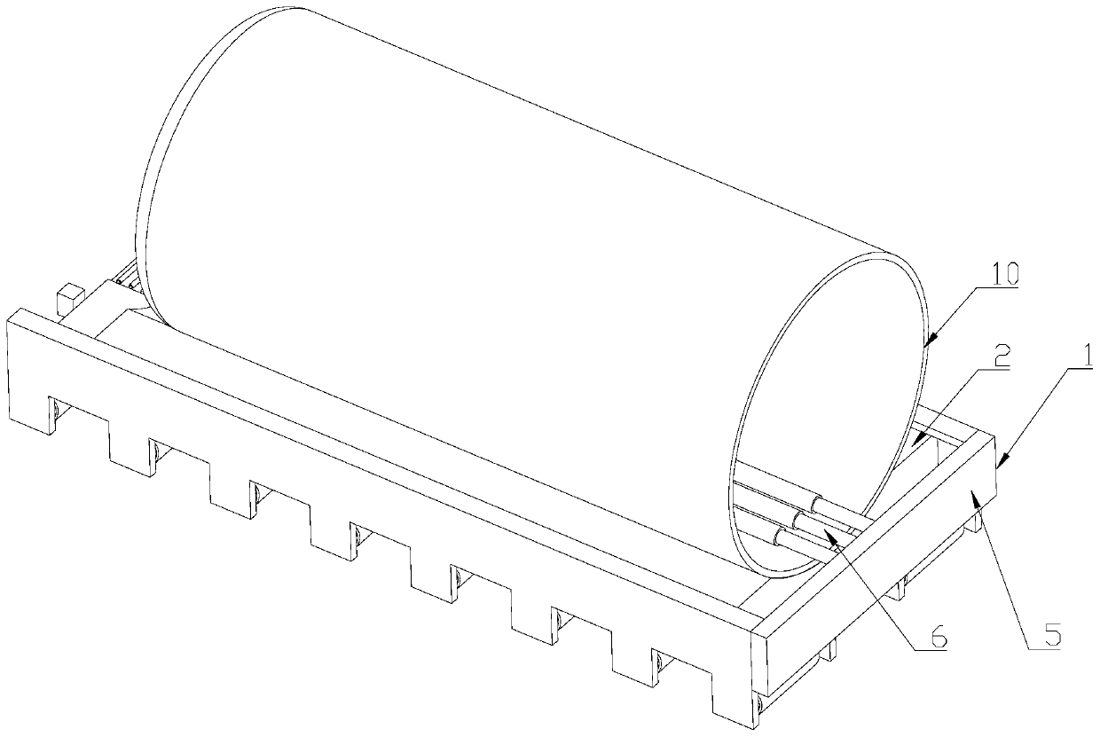
[0080] The technical solution adopted by the present invention is to combine Figure 2~3 As shown, a plane sliding propulsion device of a shield machine is provided, which includes a support frame 1, arranged on the upper side of the support frame 1, a seat plate 2 for supporting the shield machine 10, and a plurality of sliding plates arranged on the lower side of the support frame 1. The moving assembly 3 and the multiple resistance increasing assemblies 4, and the reaction force device 5 arranged at the end of the support frame 1. One end of the shield machine 10 is provided with a telescopic device 6 which is a hydraulic push cylinder. The push cylinder provides thrust and pull for the shield machine. The hydraulic push cylinder 6 is supported by the reaction device 5 to realize the advance...


PUM


Abstract

The invention aims to overcome at least one defect of the prior art and provides a propelling method for planar gliding of a shield tunneling machine. The propelling method comprises the steps that when a stretchable device stretches for propelling, a resistance-increasing assembly is started to increase the resistance, so that the acceleration of the shield tunneling machine relative to a base plate is greater than the acceleration of a supporting frame relative to the ground; and when the stretchable device retreats, the resistance-increasing assembly is started to reduce the resistance, sothat the acceleration of the shield tunneling machine relative to the base plate is smaller than the acceleration of the supporting frame relative to the ground. According to the propelling method, the maximum static friction between a propelling device and the ground in different propelling processes can be achieved only by adjusting the resistance of the resistance-increasing assembly, the stress can be switched to the resistance-increasing assembly or a gliding assembly by adjusting the height of the resistance-increasing assembly, and operation is easy; and the abrasion of the bottom of the propelling device is reduced, and the service life is prolonged.

Description

technical field [0001] The invention relates to the technical field of tunnel engineering, in particular to a planar sliding propulsion method of a shield machine. Background technique [0002] In recent years, with the rapid development of cities, the construction of urban subways has developed rapidly, and the construction of urban rail transit has become more and more popular. Shield excavation is now the main method of urban subway construction, but when encountering some complex geology, other construction methods are required. When constructing a tunnel, when the shield machine reaches the excavated tunnel, it is necessary to empty push the shield machine through the excavated tunnel section. In order to ensure that the shield machine is smoothly pushed through the excavated tunnel section, the concrete guide platform in the excavated tunnel is used as the shield body support, and the steel rail laid on the guide platform is used as the shield body walking track. As t...

Claims


Application Information

Patent Timeline
IPC IPC(8): E21D9/06
CPCE21D9/0621
Inventor 檀俊坤
Owner HENAN POLYTECHNIC UNIV
Why Eureka
Try Eureka