
Roller brush self-cleaning device of sweeper

A self-cleaning and sweeping technology, applied in the field of cleaning, can solve problems such as affecting the cleaning area of ​​the roller brush, and achieve the effect of stable cleaning degree

Pending Publication Date: 2020-01-31
合肥哈工澳汀智能科技有限公司
View PDF0 Cites 2 Cited by
  • Summary
  • Abstract
  • Description
  • Claims
  • Application Information

AI Technical Summary

Problems solved by technology

However, installing the scraper requires additional driving, which affects the cleaning area of ​​the roller brush and how to recover self-cleaning dust and other problems
[0003] Based on the above situation, because we often commercially use the sweeping robot to avoid the charging process, the attitude of the robot is fixed at this time, so we realized the self-cleaning function of the roller brush from the outside, and designed a self-cleaning platform for the sweeper roller brush. To ensure the cleanliness of the roller brush during each task

Method used


Image

  • Roller brush self-cleaning device of sweeper
  • Roller brush self-cleaning device of sweeper
  • Roller brush self-cleaning device of sweeper

Examples


Embodiment 1

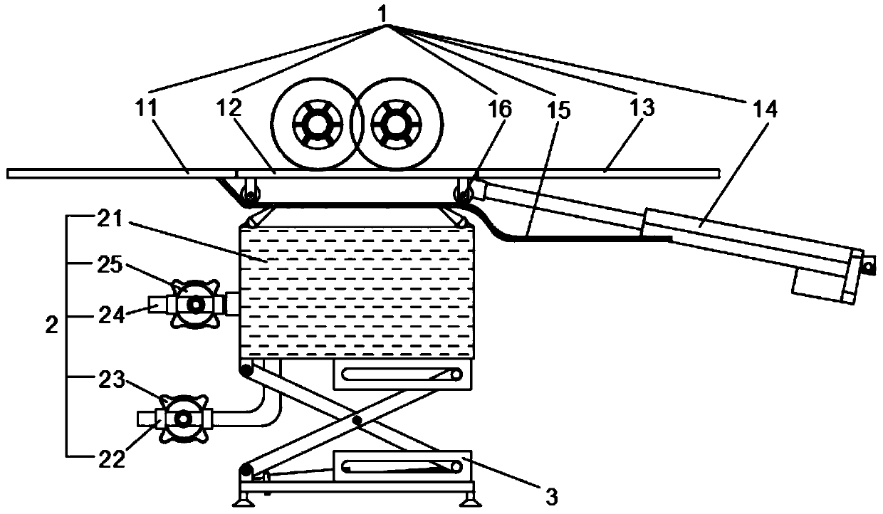
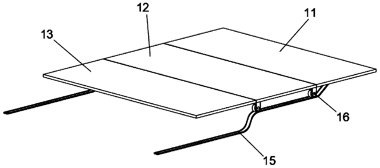
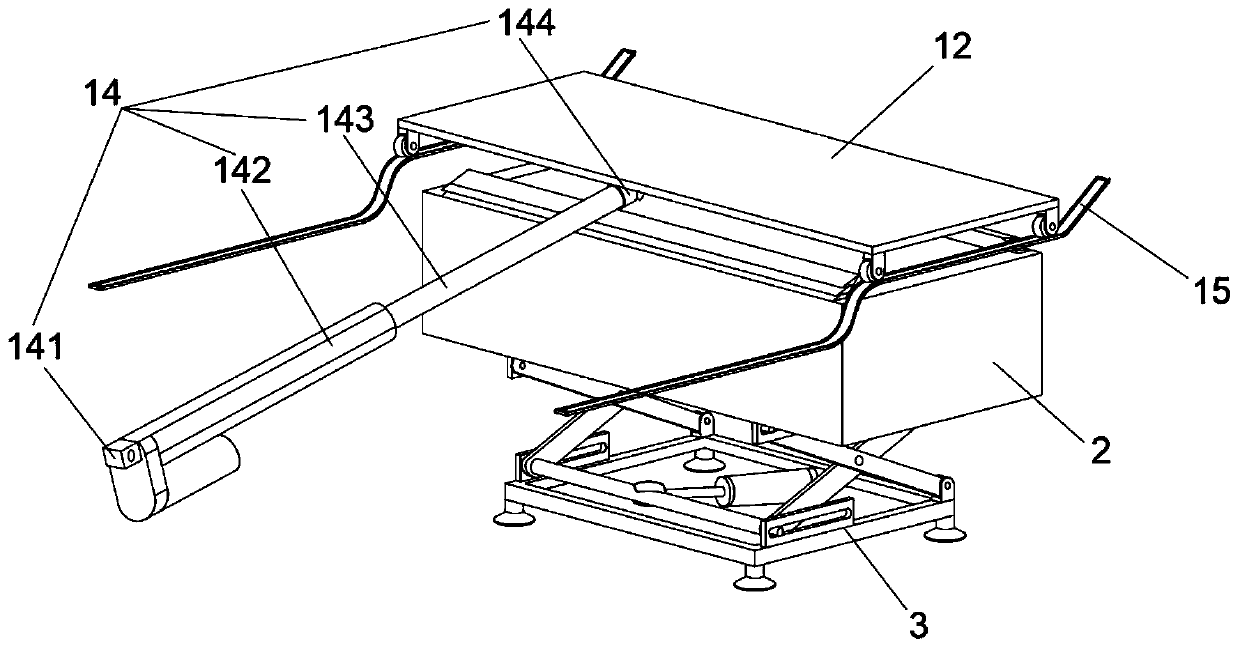
[0033] Such as figure 1 As shown, this embodiment discloses a sweeping machine roller brush self-cleaning device, including a ground opening and closing mechanism 1, a cleaning mechanism 2 and a lifting mechanism 3; the ground opening and closing mechanism 1 includes a first fixed panel 11, a moving panel 12, a second Two fixed panels 13, power assembly 14, slide rail 15 and pulley 16; figure 1 As shown, above the moving panel 12 is the roller brush of the sweeping machine. In the initial state, the roller brush of the sweeping machine is in contact with the moving panel 12, and the bristles are bent to a certain extent under the influence of pressure. The upper and lower surfaces of the first fixed panel 11 and the second fixed panel 13 overlap, leaving a gap in the width direction, and the movable panel 12 can move relative to the gravitational direction of the first fixed panel 11 and the second fixed panel 13 .

[0034] Such as figure 2 As shown, the slide rail 15 is ar...

Embodiment 2

[0042] Such as Image 6 As shown, the difference between the present embodiment and the first embodiment is that the top of the water tank 21 is provided with a limit rubber strip 211, and the limit rubber strip 211 is provided with an upper end inclined to the middle of the water tank 21; wherein the limit rubber strip 211 can be used Rubber strips are not limited to rubber strips. You can also use a water-removing structure such as a strip-based brush structure to ensure that the bristles on the roller brush can be fully dewatered and cleaned, and avoid excessive moisture from damaging the garbage box and air guide channel of the sweeper. Pollution, dust agglomerates.

[0043] Further, the four corners of the bottom of the chassis 31 are also installed with feet 311; through the setting of the feet 311, the feet 311 are in contact with the ground to support the whole mechanism.

Embodiment 3

[0045] Such as Image 6 As shown, the difference between this embodiment and Embodiment 1 and Embodiment 2 is that the inside of the water tank 21 in this embodiment has a slope structure module design, that is, in fact, part of the volume of the water tank 21 has been filled with other objects during the water injection process to avoid waste of water resources. At the same time shorten the water injection time and improve efficiency. The material filling part has a smooth slope and the lowest point, and the lowest point is a water outlet, so that all the water in the water tank 21 can flow out after cleaning is completed.


PUM


Abstract

The invention discloses a roller brush self-cleaning device of a sweeper. The roller brush self-cleaning device comprises a ground opening and closing mechanism, a cleaning mechanism and a lifting mechanism; the ground opening and closing mechanism comprises a first fixed panel, a moving panel, a second fixed panel and a power assembly; the starting end and the terminating end of the moving panelare in contact with the terminating end of the first fixed panel and the starting end of the second fixed panel respectively, and the moving panel moves relative to the gravity direction of the firstfixed panel and the second fixed panel; and the lifting mechanism is used for adjusting the position of the cleaning mechanism and enabling the cleaning mechanism to move to the end face of the top ofthe cleaning mechanism to be coincident with the terminating end face of the first fixed panel and the starting end face of the second fixing panel respectively. The cleaning mechanism is lifted to the initial position of the moving panel through the lifting mechanism by controlling the movement of the moving panel, so that the module space or manpower cleaning the rolling brush in the scraping type sweeping process can be avoided, and the idle time of the rolling brush during charging is reasonably utilized.

Description

technical field [0001] The invention relates to the field of cleaning technology, in particular to a roller brush self-cleaning device for a sweeper. Background technique [0002] With the rapid development of the robot industry, the cleaning industry is also gradually becoming more intelligent. The sweeping robot for commercial use has developed from a simple cart form to a driving form and now to a fully automatic form. The purpose of full automation is to reduce labor costs in cleaning and free humans from heavy, monotonous, and unskilled work. Therefore, the development of robots in cleaning, charging, and self-cleaning should tend to be intelligent automation. According to the existing roller brush self-cleaning technology, the design idea is to arrange a movable scraper in the axial direction of the roller brush to clean the bristles. However, the installation of the scraper requires additional driving, which affects the cleaning area of ​​the roller brush and how to ...

Claims


Application Information

Patent Timeline
Patent Type & Authority Applications(China)
IPC IPC(8): A47L11/24A47L11/40
CPCA47L11/24A47L11/4091
Inventor 赵子建祝翀宇张伟周奎于振中李文兴
Owner 合肥哈工澳汀智能科技有限公司
Learn More