Upper-side light-load single-weld-joint cargo boom

A technology for light loads and booms, applied in the direction of load hanging components, transportation and packaging, etc., can solve the problems that affect the strength of the boom, not safe and reliable, easy to open welding accidents, etc., so that it is not easy to open welding and save materials, and the effect of improving safety and reliability

Inactive Publication Date: 2020-01-31
姚运文
View PDF19 Cites 0 Cited by
  • Summary
  • Abstract
  • Description
  • Claims
  • Application Information

AI Technical Summary

Problems solved by technology

Most of the jibs of existing cranes are processed by corner welding. The welds of this kind of jib are mostly located at the corners of the jib. The welds are stressed, and the tensile and compressive strengths are less than Other non-welding positions of the boom seriously affect the strength of the boom
Therefore, this kind of multi-welded jib is relatively easy to open welding and cause accidents during use, and it is not safe and reliable to use.

Method used


Image

  • Upper-side light-load single-weld-joint cargo boom
  • Upper-side light-load single-weld-joint cargo boom
  • Upper-side light-load single-weld-joint cargo boom

Examples


Embodiment 1

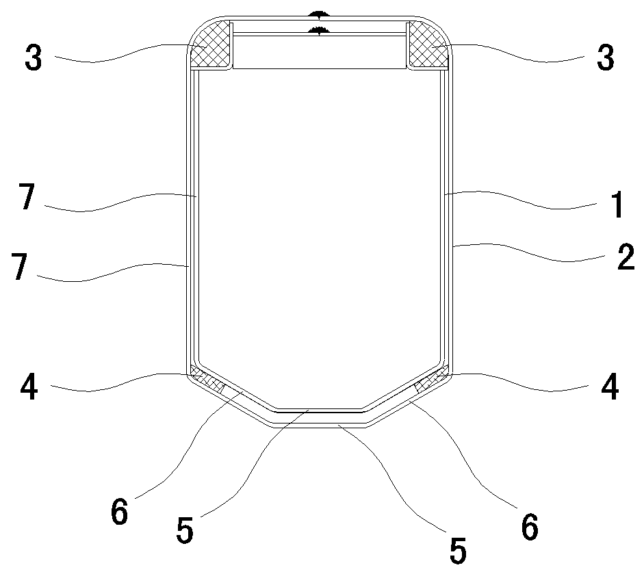
[0011] Example one, such as figure 1 As shown, it includes an inner arm 1 and an outer arm 2. The inner arm 1 is sleeved in the outer arm 2 along the extension direction of the hollow cavity of the outer arm 2. The two upper corner positions of the rear end of the inner arm 1 are respectively provided with the outer The upper sliding wear block 3 of the upper side of the arm 2 is slidingly matched with the two inner corners. The lower inner wall of the front end of the outer arm 2 is provided with a lower sliding wear block 4 that is slidingly matched with the lower outer wall of the inner arm 1. The inner arm 1 and the outer arm 2 are respectively hollow cylindrical bodies with butt edges folded from steel plates located in the middle of the upper side. The inner arm 1 and the outer arm 2 are welded into a whole at the middle butt sides of the upper side.

[0012] The butting edges of the inner arm 1 and the outer arm 2 are respectively set at the middle positions of the upper si...

Embodiment 2

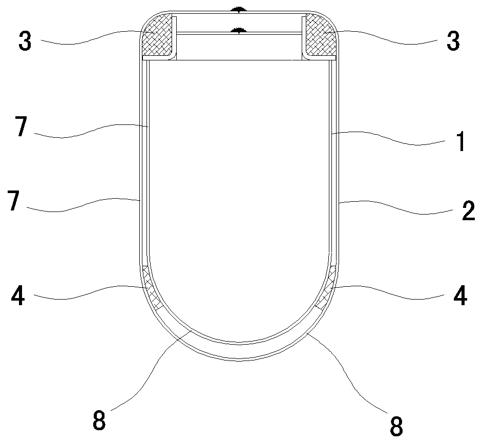
[0015] Example two, such as figure 2 As shown, the difference from the first embodiment is that the lower sides of the inner arm 1 and the outer arm 2 are the 180-degree arc-shaped surface 8 and the 180-degree arc-shaped surface 8 along the direction of the cavity of the inner arm 1 in the axial direction. The sides of the sides extend upward and parallel to each other, forming two left and right elevations 7, and the upper sides of the two elevations 7 are bent in a 90-degree arc shape. The surfaces of the grinding block 3 and the two inner corners on the upper side of the outer arm 2 are 90-degree arc-shaped surfaces, and the high points on both sides of the 180-degree arc-shaped surface 8 at the front end of the outer arm 2 are respectively provided with a lower slide The wear-resistant block 4 or the 180-degree arc-shaped surface 8 of the front end of the outer arm 2 is provided with a lower sliding wear-resistant block 4 of integral structure.

Embodiment 3

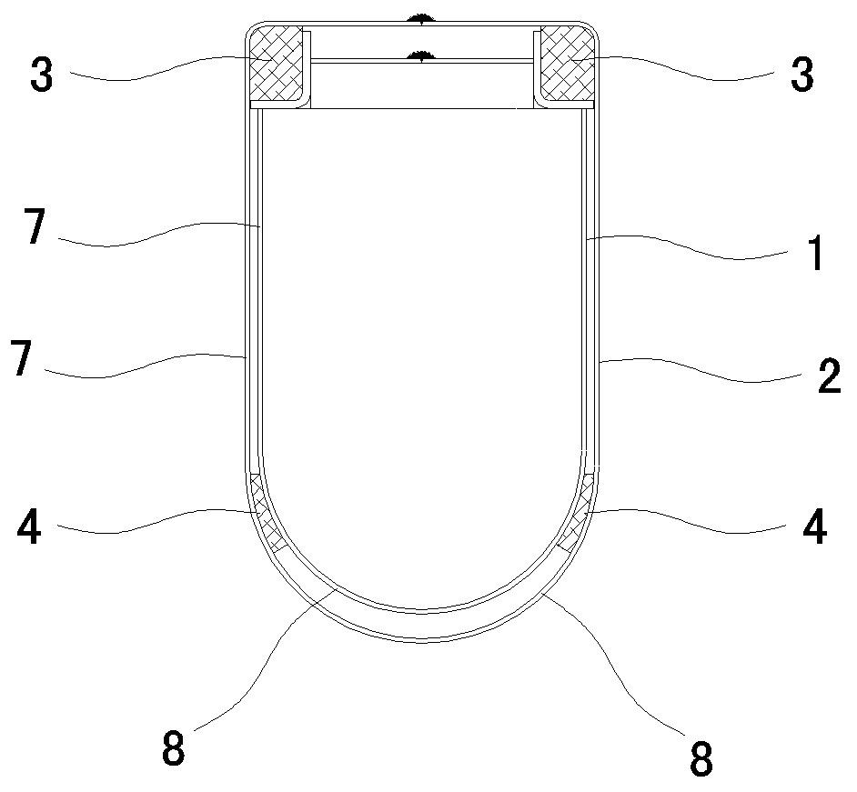
[0016] Example three, such as image 3 As shown, the difference from the first embodiment is that the lower sides of the inner arm 1 and the outer arm 2 are the 180-degree arc-shaped surface 8 and the 180-degree arc-shaped surface 8 along the direction of the cavity of the inner arm 1 in the axial direction. The sides of the sides extend upward and parallel to each other to form the left and right elevations 7 of the inner arm 1. The upper sides of the two elevations 7 are bent at right angles to each other. The surfaces of the grinding block 3 and the two inner corners on the upper side of the outer arm 2 are right-angled surfaces, and a lower sliding wear-resistant block is provided on both sides of the high point of the 180-degree arc-shaped surface 8 at the front end of the outer arm 2 respectively 4. Or the 180-degree arc-shaped surface 8 of the front end of the outer arm 2 is provided with a lower sliding wear block 4 of integral structure.


PUM


Abstract

The invention relates to an upper-side light-load single-weld-joint cargo boom. The upper-side light-load single-weld-joint cargo boom comprises an inner boom (1) and an outer boom (2). The inner boom(1) is sleeved with the outer boom (2) in the stretching direction of a hollow cavity of the outer boom (2), the inner boom (1) and the outer boom (2) are hollow barrel-shaped bodies which are formedby bending steel plates and provided with butt joint sides located at the middle position of the upper side face, and the inner boom (1) and the outer boom (2) are welded into a whole at the positions of the butt joint sides in the middle of the upper side face separately. The upper-side light-load single-weld-joint cargo boom is high in strength, low in weight, not prone to breakage and high inuse reliability. Only one weld joint is arranged at the middle position of the upper side face of the cargo boom, an overall structure adopting welding at the middle position of the upper side face isformed by the cargo boom, bearing force on the weld joint is greatly reduced, thus, the problem of breakage caused by bearing of the weld joint is avoided, and the safety and the reliability of the cargo boom are directly improved.

Description

Technical field [0001] The invention relates to lifting equipment, in particular to a lifting arm. Background technique [0002] The boom is a key component of the crane. In order to improve the lifting capacity, crane manufacturers need to adopt various methods to reduce the weight of the boom. However, the prerequisite for reducing the weight of the boom is that the strength of the boom cannot be reduced. Practical and reasonable improvements are made to the structure of the heavy boom. Most of the booms of the existing cranes are processed by corner welding. The welds of this type of boom are mostly set at the corners of the boom. The welds are stressed, and the tensile and compressive strengths are less than The other non-welding positions of the boom seriously affect the strength of the boom. Therefore, the multi-welded boom is easier to open welding and cause accidents during use, and it is not safe and reliable to use. Summary of the invention [0003] The purpose of the...

Claims


Application Information

Patent Timeline
Patent Type & Authority Applications(China)
IPC IPC(8): B66C13/00
CPCB66C13/00
Inventor 姚运文姚婧辉
Owner 姚运文
Why Eureka
Try Eureka