Film bioreactor and sewage treatment process

A membrane bioreactor, sewage treatment technology, applied in water/sewage treatment, sustainable biological treatment, water/sewage treatment equipment, etc., can solve problems such as poor denitrification and phosphorus removal efficiency

Inactive Publication Date: 2020-01-31
POTEN ENVIRONMENT GRP +2
View PDF6 Cites 0 Cited by
  • Summary
  • Abstract
  • Description
  • Claims
  • Application Information

AI Technical Summary

Problems solved by technology

[0004] The purpose of the embodiment of this application is to provide a membrane bioreactor and sewage treatment process, w

Method used


Image

  • Film bioreactor and sewage treatment process
  • Film bioreactor and sewage treatment process
  • Film bioreactor and sewage treatment process

Examples


Embodiment 1

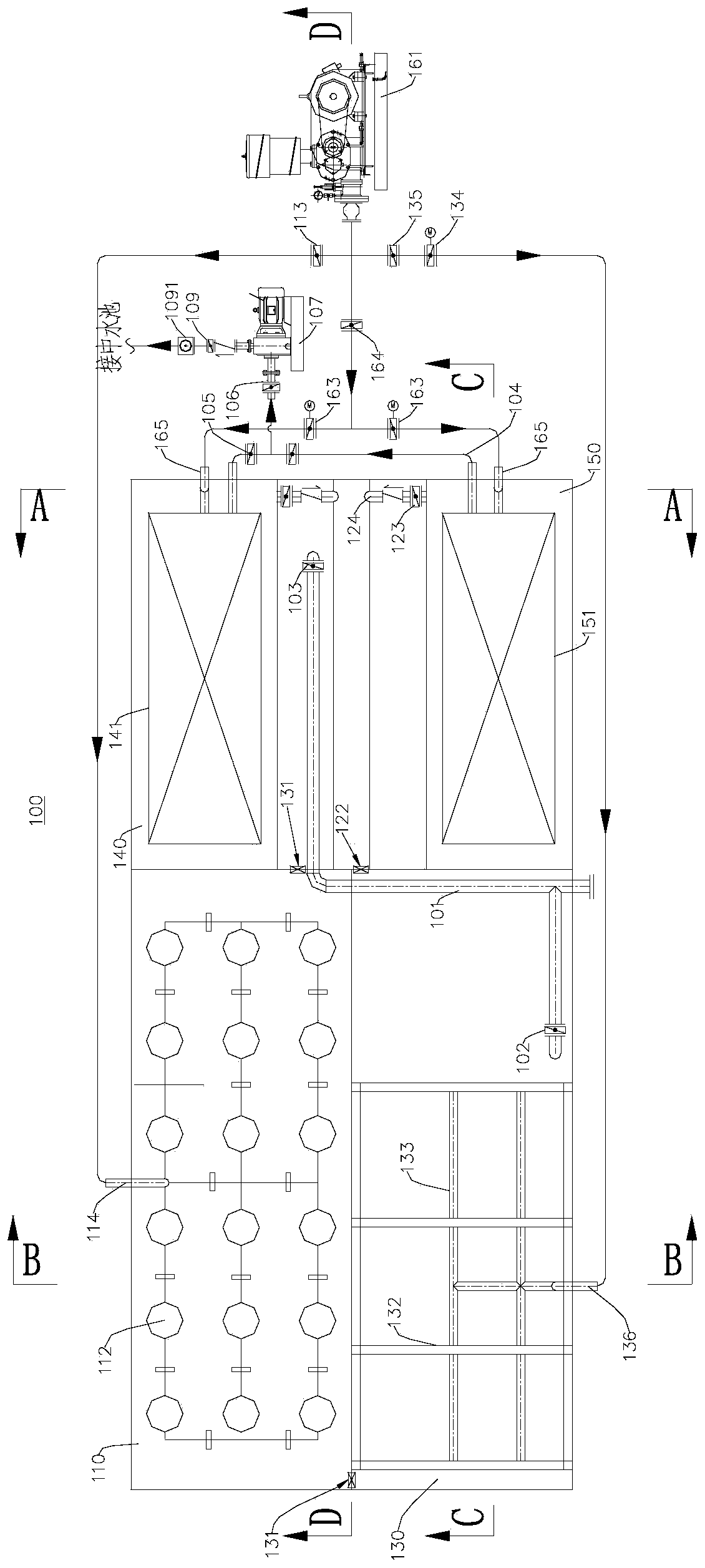
[0045] figure 1 A schematic structural diagram of the membrane bioreactor 100 provided by the embodiment of the present application is shown, please refer to figure 1 . This embodiment provides a membrane bioreactor 100, which is mainly used for sewage treatment.

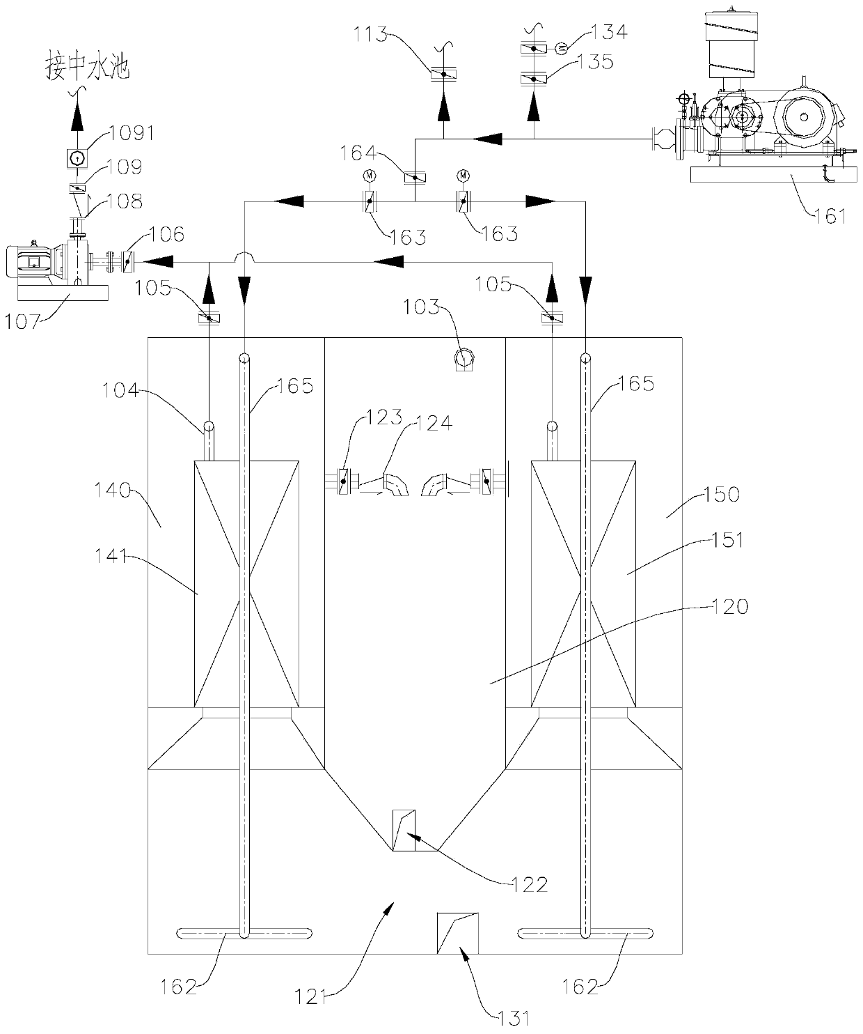
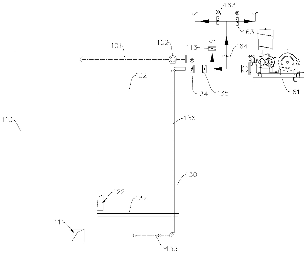
[0046] The membrane bioreactor 100 includes an aerobic tank 110 , an anoxic tank 120 , an anaerobic tank 130 and two membrane tanks, and the two membrane tanks are respectively named as a first membrane tank 140 and a second membrane tank 150 .

[0047] The aerobic pool 110 and the anoxic pool 120 are separated by a partition, the anaerobic pool 130 and the aerobic pool 110 are separated by a partition, and the anaerobic pool 130 and the anoxic pool 120 are separated by a partition . The first film pool 140 and the second film pool 150 are arranged on both sides of the anoxic pool 120, and the first film pool 140 and the second film pool 150 are separated from the anaerobic pool 130 and the aerobic pool 110 with ...

Embodiment 2

[0106] This embodiment provides a sewage treatment process, using the membrane bioreactor 100 provided in Example 1 for sewage treatment.

[0107] see Figure 1-Figure 5 and Example 1.

[0108] The process of sewage treatment mainly includes:

[0109] The sewage is transported through the anaerobic pool 130 and the anoxic pool 120, and then enters the first membrane pool 140 or the second membrane pool 150 through the aerobic pool 110, and is output after being purified. In the process of sewage treatment, the sludge in the membrane bioreactor 100 is circulated as follows:

[0110] Aerobic pool 110——Aerobic pool Membrane pool sludge channel 111—Membrane pool—Sludge return regulating valve 123—Check valve 124—Anoxic pool 120—Anoxic anaerobic sludge channel 122— —anaerobic pool 130 —anaerobic-aerobic sludge channel 131 —aerobic pool 110.

[0111]Further, in this embodiment, the suction pump 107 that sucks the purified water into the membrane tank operates intermittently. Th...


PUM


Abstract

The invention relates to the field of water treatment, in particular to a film bioreactor and a sewage treatment process. The film bioreactor comprises an anoxic tank, film tanks, an anaerobic tank and an aerobic tank. The two film tanks can be communicated through a film tank channel; and the film tank is communicated with the anoxic tank through a sludge reflux regulating valve. The anaerobic tank can be communicated with the anoxic tank through an anoxic and anaerobic sludge channel arranged at the bottom of the anoxic tank; and the aerobic tank can be communicated with the film tank through an aerobic tank and film tank sludge channel arranged at the bottom of the aerobic tank. And the aerobic tank and the anaerobic tank can be communicated through an anaerobic-aerobic sludge channel arranged at the bottom of the anaerobic tank. Sludge in the film bioreactor in the embodiment circularly flows in a closed manner in the film bioreactor. One-way flow of the sludge is automatically formed in the film bioreactor under the action of airlift circulation, and the effect of a sludge reflux pump is replaced, so that the energy consumption is reduced; meanwhile, the sludge activity can becontinuously converted in aerobic, anaerobic and anoxic environments, so that the purposes of nitrogen and phosphorus removal are achieved.

Description

technical field [0001] The application relates to the field of water treatment, in particular, to a membrane bioreactor and a sewage treatment process. Background technique [0002] MBR, also known as Membrane Bio-Reactor (Membrane Bio-Reactor), is a new type of water treatment technology that combines a membrane separation unit with a biological treatment unit. [0003] In the actual operation process, the low-consumption integrated MBR equipment is formed by partitioning the reaction pool through partitions, which are divided into membrane pools, anoxic pools and anaerobic pools peripheral to the membrane pools. Under normal circumstances, under the action of aeration, the mixed sludge in the membrane tank flows out of the membrane tank due to the large amount of aeration, that is, flows to the anoxic tank and the anaerobic tank, and the activated sludge naturally experiences anaerobic Aerobic anaerobic environment, the effect of nitrogen and phosphorus removal is better....

Claims


Application Information

Patent Timeline
IPC IPC(8): C02F3/30C02F7/00
CPCC02F3/30C02F7/00C02F2201/007C02F2301/043C02F2301/08Y02W10/10
Inventor 赵曙光李亚耿翠玉陈士伟迟娟姜勇
Owner POTEN ENVIRONMENT GRP
Why Eureka
Try Eureka