
Cutter device of shield tunneling machine

A shield machine tool and shield machine technology, applied in the field of shield machines, can solve the problems of displacement use of internal output groups, high cost requirements, and failure to meet heat dissipation requirements, and achieve the effect of preventing displacement.

Pending Publication Date: 2020-01-31
湖南合盾工程刀具有限公司
View PDF0 Cites 0 Cited by
  • Summary
  • Abstract
  • Description
  • Claims
  • Application Information

AI Technical Summary

Problems solved by technology

[0004] The purpose of the present invention is to provide a shield machine cutter device in order to solve the above problems, which solves the problem that the existing self-cooling and self-fan cooling do not meet the heat dissipation requirements, and the cost requirement of forced heat dissipation is too high, so the above three None of these is the best way to dissipate heat. At the same time, the motor vibrates during operation for a long time, which may easily cause displacement of the internal output group and affect the use of the problem.

Method used


Image

  • Cutter device of shield tunneling machine
  • Cutter device of shield tunneling machine
  • Cutter device of shield tunneling machine

Examples


Embodiment Construction

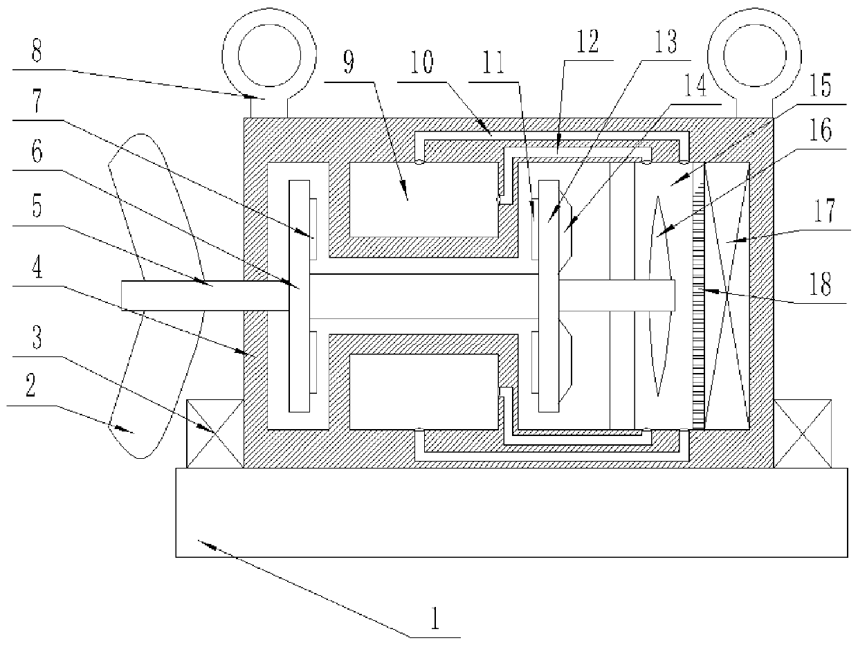
[0020] Such as figure 1 , This specific embodiment adopts the following technical solutions: a shield machine tool device, including a shield machine base 1, a blade 2, an anti-displacement fixed plate 3, a waterproof outer cover 4, a rotating shaft 5, a first rotating plate 6, and a first coil 7. Lifting ring 8, cooling groove 9, first pipe 10, second coil 11, second pipe 12, second rotating plate 13, permanent magnet 14, return tank 15, magnetic transmission wheel 16, refrigeration device 17, and temperature guide plate 18; The blade 2 is fixedly connected to the rotating shaft 5; the upper surface of the shield machine base 1 is fixedly connected with a waterproof cover 4, the left and right ends of the waterproof cover 4 are provided with anti-displacement fixing plates 3; the waterproof cover 4 Both sides of the upper end are fixedly connected with a lifting ring 8; the inner right end of the waterproof housing 4 is provided with a refrigeration device 17, and the left end ...


PUM


Abstract

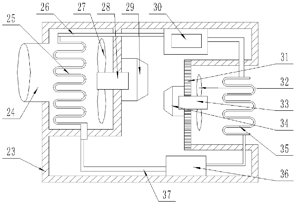
The invention discloses a cutter device of a shield tunneling machine. The cutter device comprises a shield tunneling machine base, a blade, an anti-displacement fixing plate, a waterproof outer cover, a rotating shaft, a first rotating plate, first coils, a lifting ring, a cooling groove, a first pipeline, second coils, a second pipeline and the like. According to the cutter device of the shieldtunneling machine, a magnetic transmission wheel in a return water tank obtains power from the rotating shaft, and the water flow is driven to flow into the cooling groove from the first pipeline andflow back to the return water tank through the second pipeline to achieve the circulating purpose. According to the cutter device of the shield tunneling machine, high-temperature low-pressure gas issucked by a compressor from an evaporator in a refrigeration device, the gas is compressed by the compressor and turned into high-temperature high-pressure liquid and enters a condenser, the condenserdissipates heat to the outside, a second motor drives second fans to blow hot air to the outer side of the device, the condenser turns the high-temperature high-pressure liquid into low-temperature high-pressure liquid, the low-temperature high-pressure liquid is turned into low-temperature low-pressure liquid through an expansion valve and enters the evaporator, and through evaporation by the evaporator and exchange with high-temperature gas, circulation is achieved.

Description

Technical field: [0001] The invention relates to the technical field of shield machines, in particular to a shield machine cutter device. Background technique: [0002] The shield machine is a tunnel boring machine that uses the shield method. The shield construction method is to construct (lay) the "shield" (referring to supporting segments) of the tunnel while the tunneling machine is driving, which is different from the open construction method. [0003] Shield machine tool device is driven by the motor to drive the tool to rotate. The motor will inevitably generate a lot of heat during operation. The main reasons are bearing friction, coil resistance, iron core reluctance, etc., which will all be in the running process of the motor. The temperature of the medium motor is getting higher and higher. When the temperature of the motor is too high, it will cause the motor to malfunction and seriously shorten the service life of the motor. Now the main methods of cooling the motor a...

Claims


Application Information

Patent Timeline
Patent Type & Authority Applications(China)
IPC IPC(8): E21D9/08F25B1/00
CPCE21D9/08F25B1/00
Inventor 刘迎黄雄凌峰
Owner 湖南合盾工程刀具有限公司
Learn More