Driving circuit of quick tripping relay

A technology for driving circuits and relays, applied to relays, circuits, electrical components, etc., can solve the problem of reducing the pull-in time and achieve the effect of shortening the pull-in time

Pending Publication Date: 2020-01-31
EXAMING & EXPERIMENTAL CENT OF ULTRAHIGH VOLTAGE POWER TRANSMISSION COMPANY CHINA SOUTHEN POWER GRID
View PDF0 Cites 0 Cited by
  • Summary
  • Abstract
  • Description
  • Claims
  • Application Information

AI Technical Summary

Problems solved by technology

Therefore, the pull-in time of the existing fast tripping relay needs to be further reduced

Method used


Image

  • Driving circuit of quick tripping relay

Examples


Embodiment Construction

[0016] In order to make the above objects, features and advantages of the present invention more comprehensible, the present invention will be further described in detail below in conjunction with the accompanying drawings and specific embodiments.

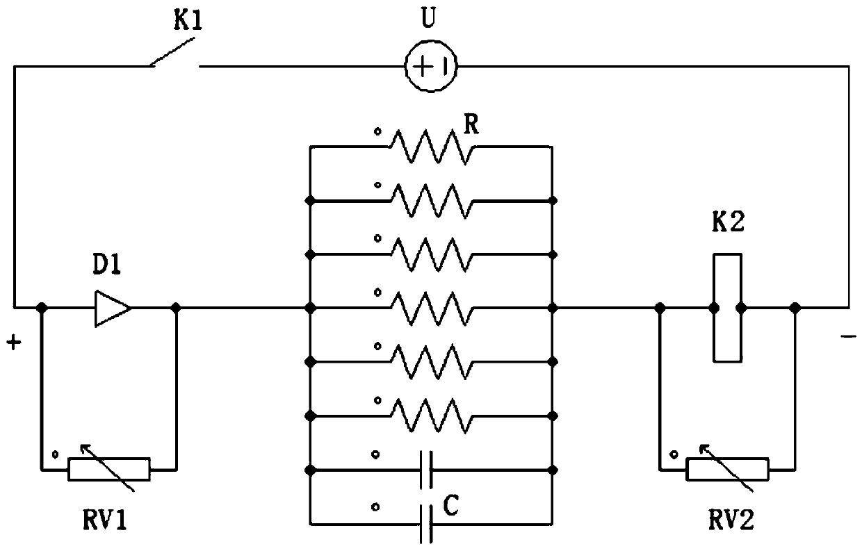
[0017] Please refer to figure 1 As shown, a driving circuit of a fast tripping relay in this embodiment includes a 110V DC voltage source U, a switch K1, a coil K2 with a rated operating voltage of 16V, six resistors R with a resistance value of 18KΩ, two Capacitor C with capacitance value of 22uF, diode D1, varistor RV1 and varistor RV2. When the relay needs to work, close the switch K1, so that the 110V DC voltage source U is connected; when the relay does not need to work, turn off the switch K1, and the relay stops working.

[0018] Six resistors R and two capacitors C are connected in parallel to form an RC parallel circuit, the DC voltage source U is connected to the anode of the diode D1 through the switch K1, the cathode ...


PUM


Abstract

The invention discloses a driving circuit of a rapid tripping relay. The driving circuit comprises a direct-current voltage source U, a switch K1, a coil K2, an RC parallel circuit and a diode D1; thepositive electrode of the direct-current voltage source U is connected with the positive electrode of the diode D1 through the switch K1; the negative electrode of the diode D1 is connected with oneend of the RC parallel circuit; the other end of the RC parallel circuit is connected with the positive electrode of the coil K2; the negative electrode of the coil K2 is connected with the negative electrode of the direct-current voltage source U; and the rated working voltage of the coil K2 is smaller than that of the direct-current voltage source U. With the driving circuit of the rapid tripping relay adopted, the pull-in time of the relay can be shortened; a condition that the relay is connected into a reverse direct-current voltage source and is damaged can be eliminated; current freewheeling and arc extinction can be realized at the moment when the relay coil is powered off; and the diode and the coil can be protected.

Description

technical field [0001] The invention relates to the technical field of high-voltage direct current transmission, in particular to a driving circuit for a fast tripping relay. Background technique [0002] The fast trip relay is used for the AC filter protection screen and the DC protection interface screen of the HVDC power transmission project. When the relay protection operates, the protection screen sends out a signal to pressurize the excitation coil of the fast trip relay. After a certain delay, the relay closes , that is, close the trip coil of the circuit breaker at the next level, and then the circuit breaker trips. Since the relay protection requires the fault source to be cut off quickly, the delay from the pressurization to the closing of the relay is required to be at the ms level, that is, the relay pull-in time is at the ms level. Therefore, the pull-in time of the existing fast tripping relay needs to be further reduced. Contents of the invention [0003] ...

Claims


Application Information

Patent Timeline
Patent Type & Authority Applications(China)
IPC IPC(8): H01H47/32
CPCH01H47/32
Inventor 刘坤王振唐金昆梁宁邹延生
Owner EXAMING & EXPERIMENTAL CENT OF ULTRAHIGH VOLTAGE POWER TRANSMISSION COMPANY CHINA SOUTHEN POWER GRID
Why Eureka
Try Eureka