A High Voltage Fast Phase Change Switch
A commutation switch, high-voltage technology, applied in the direction of reducing the asymmetry of the multi-phase network, eliminating/reducing the asymmetry of the multi-phase network, etc., can solve the problems of increasing line loss, generating large inrush current, reducing power supply reliability, etc., and achieving Reduce the switching time, reduce the pull-in time, and ensure the effect of timeliness
- Summary
- Abstract
- Description
- Claims
- Application Information
AI Technical Summary
Problems solved by technology
Method used
Image
Examples
specific Embodiment approach 1
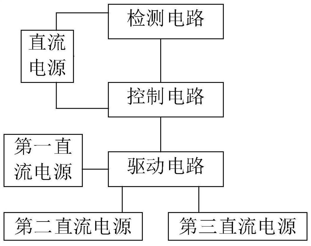
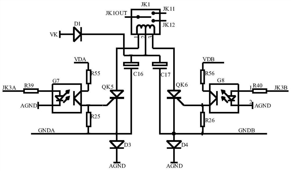
[0033] A kind of high-voltage fast commutation switch of the present invention, such as figure 1 As shown, it includes four independent DC power supplies, detection circuits, drive circuits, and control circuits. The detection circuit is used to detect the state of AC power and output detection signals. The control circuit is used to output control signals according to the detection signals. The drive circuit is used for all The state of the commutation switch is switched by the control signal, the control circuit is connected with the detection circuit and the drive circuit, and the three independent DC power sources are used for the drive circuit to release energy without affecting each other. The fourth DC power supply is used to supply power to the control circuit and the detection circuit.
[0034] The control circuit includes an MCU and a register. The register is a serial-in-parallel-out register, which is used to convert the serial control signal output by the MCU into...
specific Embodiment approach 2
[0053] The connection relationship of the commutation switch in the three-phase alternating current is as follows: figure 2 As shown, the main switch JK1 of the commutation switch is used for on-off control of the three-phase alternating current, and the auxiliary switches JK2 and JK3 are used for selecting one phase of the three-phase alternating current to be turned on.
[0054] The two switch terminals of the auxiliary switch JK3 are respectively connected to the A-phase and B-phase AC input terminals, and its common terminal is connected to one switch terminal of the auxiliary switch JK2, and the other switch terminal of the auxiliary switch JK2 is connected to the C-phase AC input terminal, and the auxiliary switch JK2 The common end of the main switch JK1 is connected to one switch end of the main switch JK1, the other switch end of the main switch JK1 is suspended, and the common end of the main switch JK1 is connected to the input end of the main circuit.
[0055] The...
specific Embodiment approach 3
[0073] The control circuit is connected to the output terminal of the detection circuit, such as Figure 5 As shown, the detection circuit includes a zero-crossing detection circuit and a state detection circuit; the zero-crossing detection circuit includes three zero-crossing detection sub-circuits, which are respectively used to detect the zero-crossing point of each phase of alternating current.
[0074] In this embodiment, the three zero-crossing detection sub-circuits have the same structure, such as Figure 6 shown.
[0075] Including optocoupler G4 for isolation of AC and DC power.
[0076] One input end of the control side of the optocoupler G4 is connected to the A-phase alternating current through the resistor R3, and its output end is connected to the neutral line through the resistor R4. An output terminal on the output side of the optocoupler G4 is connected to the base of the triode Q2, connected to the power supply terminal AVCC of the fourth DC power supply t...
PUM
 Abstract
Description
Claims
Application Information
 - R&D
- Intellectual Property
- Life Sciences
- Materials
- Tech Scout
- Unparalleled Data Quality
- Higher Quality Content
- 60% Fewer Hallucinations
Browse by: Latest US Patents, China's latest patents, Technical Efficacy Thesaurus, Application Domain, Technology Topic, Popular Technical Reports.
© 2025 PatSnap. All rights reserved.Legal|Privacy policy|Modern Slavery Act Transparency Statement|Sitemap|About US| Contact US: help@patsnap.com


