Data transmitter and data receiver

a data transmitter and receiver technology, applied in the field of data transmitters and data receivers, can solve the problems of adverse increase in jitter, increase in cost, and corresponding complexity of connection structures, and achieve the effect of simplifying the circuit design of data receivers and reducing the manufacturing cost of receivers

Inactive Publication Date: 2013-01-08
PANASONIC CORP
View PDF27 Cites 0 Cited by
  • Summary
  • Abstract
  • Description
  • Claims
  • Application Information

AI Technical Summary

Benefits of technology

The patent is about a way to transmit video and audio data over a single network cable. This is done by using existing methods for transmitting video data, while also sending a special frequency division parameter and a count value from the transmitting end. The receiving end then uses these parameters to generate an audio clock that helps reduce the time it takes to synchronize with the video data. This also makes it easier to change the pixel clock or audio data sampling frequency during data receiving. Overall, this method simplifies the circuit design of the data receiver and reduces manufacturing costs.

Problems solved by technology

However, when the video data and the audio data are transmitted from the video / audio signal source 700 to the display unit 710 using the two separate cables for video data and audio data as shown in FIG. 31, the connection structure correspondingly becomes complicated.
However, in order to perform data transmission using the IEEE1394 bus line, very complicated data processing is required, whereby a structure on a transmitting end for encoding data to be transmitted, or a structure on a receiving end for decoding data that is received via the bus line needs quite a large circuit construction, resulting in an increased cost.
Further, as a high-speed signal is transmitted through the signal line for the audio clock transmission, jitter is adversely increased.

Method used


Image

  • Data transmitter and data receiver
  • Data transmitter and data receiver
  • Data transmitter and data receiver

Examples


embodiment 1

[0114]Hereinafter, an embodiment of the present invention will be described with reference to the figures.

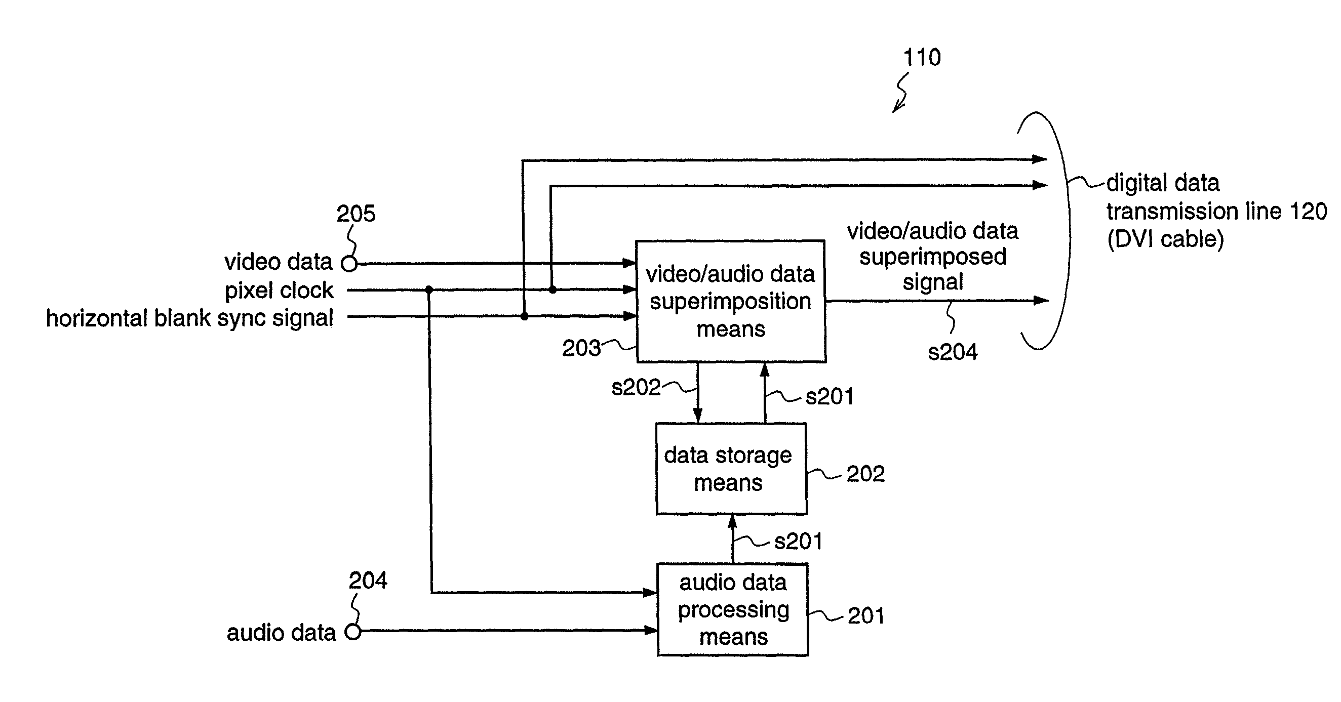
[0115]A digital data transmission system according to this embodiment is adapted to transmit video data and audio data that are outputted from a video / audio signal source, such as a videocassette tape recorder / player, a video disk player, or a tuner, to a display unit such as a monitor receiver having a sound output function or a television receiver, through one transmission cable. Here, a cable that transmits data based on a standard which is referred to as DVI (Digital Visual Interface) is utilized for the transmission cable.

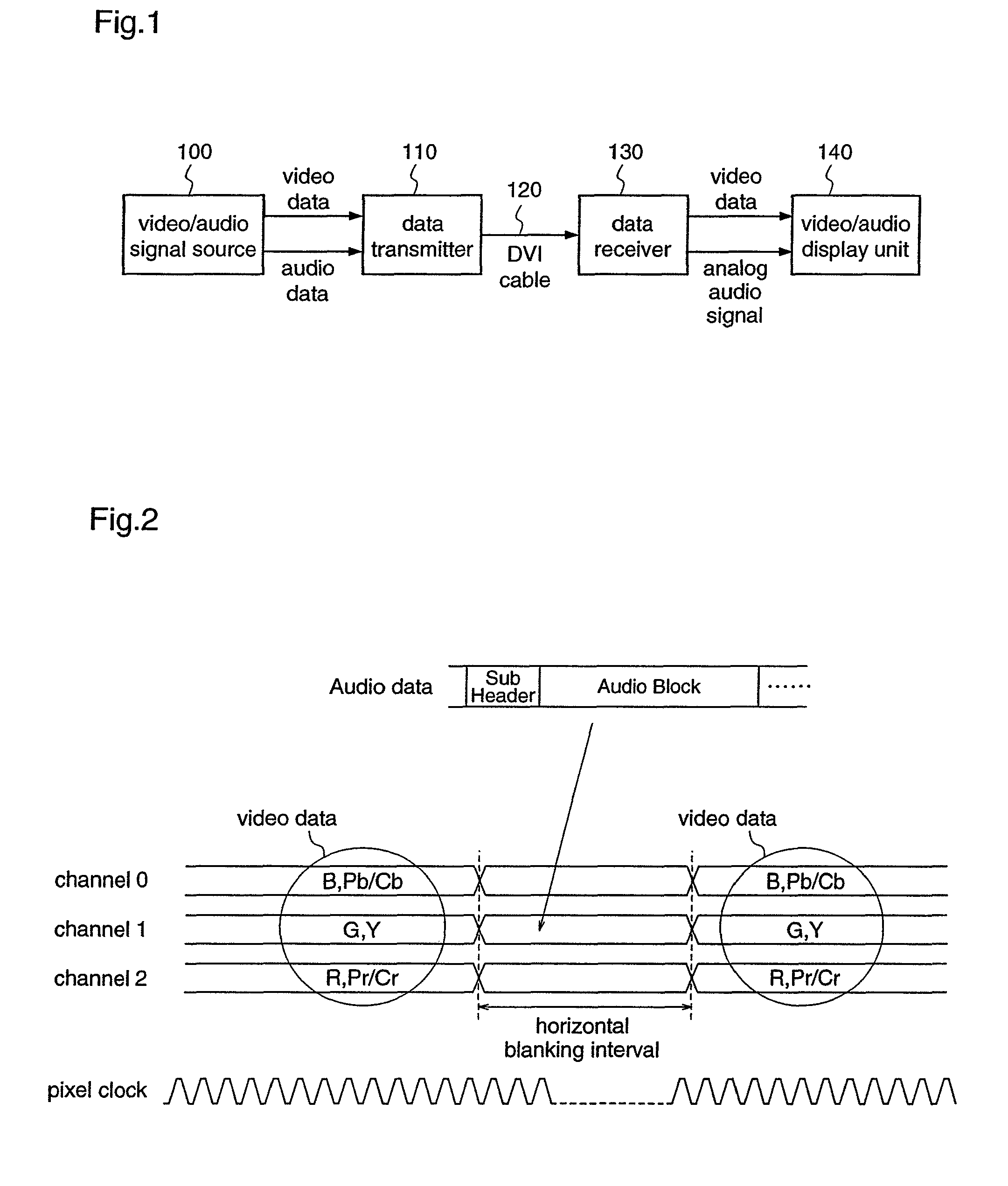
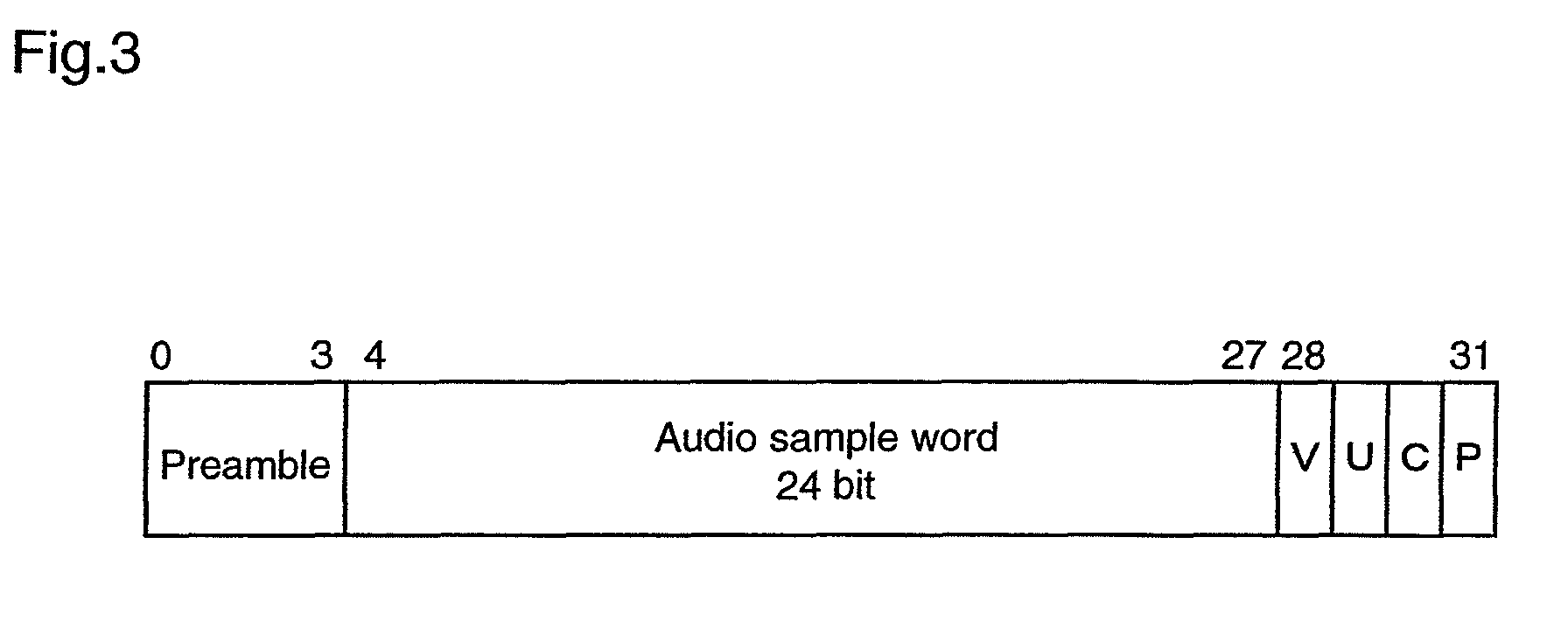
[0116]Initially, the digital data transmission system according to the embodiment will be described with reference to FIGS. 1 to 3.

[0117]FIG. 1 is a diagram illustrating an entire construction of a digital data transmission system according to this embodiment. In this figure, reference numeral 100 denotes a video / audio signal source such as a videotape rec...


PUM


Abstract

As shown in FIG. 7, a data receiver receives video data and audio data together with a frequency division parameter N that depends on the pixel clock of the video data and the sampling frequency of the audio data, and a count value CTS that is obtained by counting the period of the audio clock that has been subjected to frequency division by the frequency division parameter N, with the pixel clock, which are transmitted from a data transmitter, and subjects the pixel clock to frequency division by the count value CTS, phase-control the divided clock (s501) in accordance with a phase comparison clock (s505) that is obtained by dividing an audio clock (s403) oscillated from a VCO (504) by the frequency division parameter N, thereby generating an audio clock (s403).Accordingly, the data transmitter and the data receiver can satisfactorily implement multiplexing of audio data and video data, and transmission of the multiplexed data using an existing DVI cable, with a simple structure.

Description

[0001]This is a Rule 1.53(b) Divisional of application Ser. No. 10 / 485,769 now U.S. Pat. No. 7,855,751, which is the National Stage of International Application No. PCT / JP03 / 07462, filed Jun. 12, 2003.TECHNICAL FIELD[0002]The present invention relates to a data transmitter and a data receiver in a digital data transmission system in which a video signal source and a video display unit are connected, for example, through a DVI (Digital Video Interface) and, more particularly, to a data transmitter and a data receiver that can easily and satisfactorily transmit audio data through an existing interface for transmitting video data.BACKGROUND ART[0003]Recently, a standard that is referred to as DVI has been standardized for transmitting video data to a display unit in digital format when a video signal source such as a television tuner, a video player, or a personal computer device is connected to a video display unit such as a monitor receiver.[0004]Details of the DVI standard are given...

Claims


Application Information

Patent Timeline
Patent Type & Authority Patents(United States)
IPC IPC(8): H04N7/12H04N7/08H04H1/00H04H20/28H04N5/04H04N5/12H04N5/60H04N7/081H04N7/083H04N7/084H04N7/085H04N9/475H04N9/64
CPCH04H20/28H04N21/43632H04N7/083H04N9/641H04N21/4305H04N5/04H04N5/126H04N5/602H04N7/08
Inventor EJIMA, NAOKI
Owner PANASONIC CORP
Why Eureka
Try Eureka