
Clamp suction row and transfer clamp of same

A fixture and transfer technology, which is applied in the field of fixture suction and transfer and its transfer fixture, can solve the problems of inconvenient and precise control, unbalanced suction of the suction cup, and easily damaged circuit boards, so as to improve safety and accuracy and reduce the board drop rate , the effect of increasing applicability

Pending Publication Date: 2020-02-04
GUANGZHOU TAILI ELECTRICAL & MECHANICAL EQUIP CO LTD
View PDF0 Cites 1 Cited by
  • Summary
  • Abstract
  • Description
  • Claims
  • Application Information

AI Technical Summary

Problems solved by technology

[0003] (1) The suction and discharge of the existing fixtures, the suction force of each suction cup is unbalanced.
[0004] (2) It is inconvenient to add suction cups to the existing fixture suction and discharge. For circuit boards of different sizes and weights, the number of suction cups required is different. Strong; but the existing fixture suction and discharge is not convenient to add a suction cup
[0005] (3) When the suction cup picks and places the circuit board, if it is too aggressive, it will easily damage the circuit board; during the moving process, there will be moving vibration, and the vibration will easily cause the adsorption instability and cause the board to fall
[0006] (4) The existing transfer fixture cannot be applied to circuit boards of different sizes
[0007] (5) The existing transfer fixture is not convenient for precise control

Method used


Image

  • Clamp suction row and transfer clamp of same
  • Clamp suction row and transfer clamp of same
  • Clamp suction row and transfer clamp of same

Examples


Embodiment Construction

[0035] The present invention is described in further detail now in conjunction with accompanying drawing. These drawings are all simplified schematic diagrams, which only illustrate the basic structure of the present invention in a schematic manner, so they only show the configurations related to the present invention.

[0036] In the description of the present application, it should be understood that the terms "longitudinal", "radial", "length", "width", "thickness", "upper", "lower", "left", "right", " The orientation or positional relationship indicated by "front", "rear", "vertical", "horizontal", "top", "bottom", "inner", "outer", etc. is based on the orientation or positional relationship shown in the drawings, It is only for the convenience of describing the present invention and simplifying the description, but does not indicate or imply that the device or element referred to must have a specific orientation, be constructed and operated in a specific orientation, and ...


PUM


Abstract

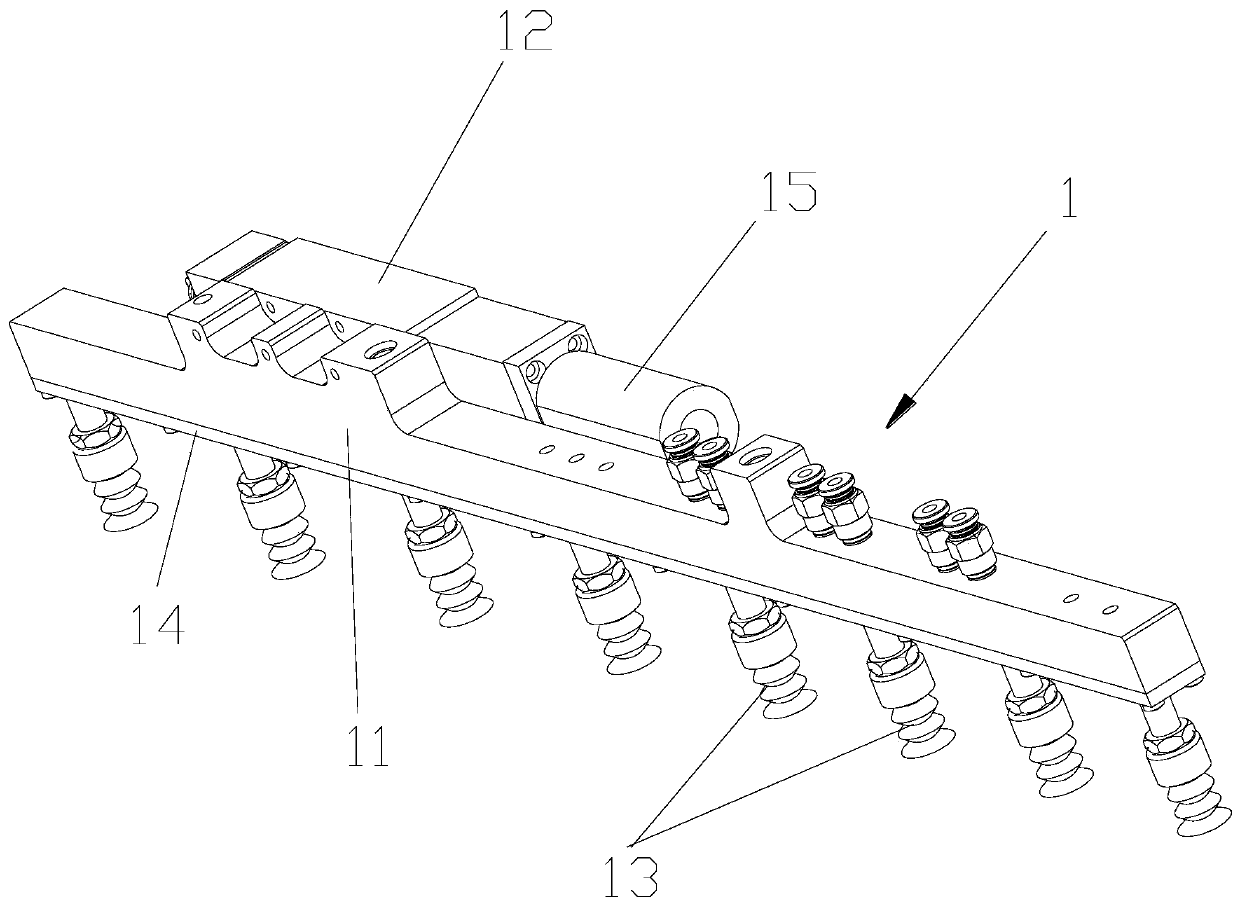
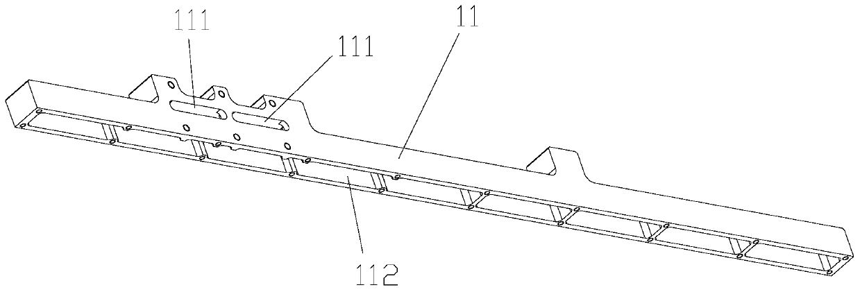
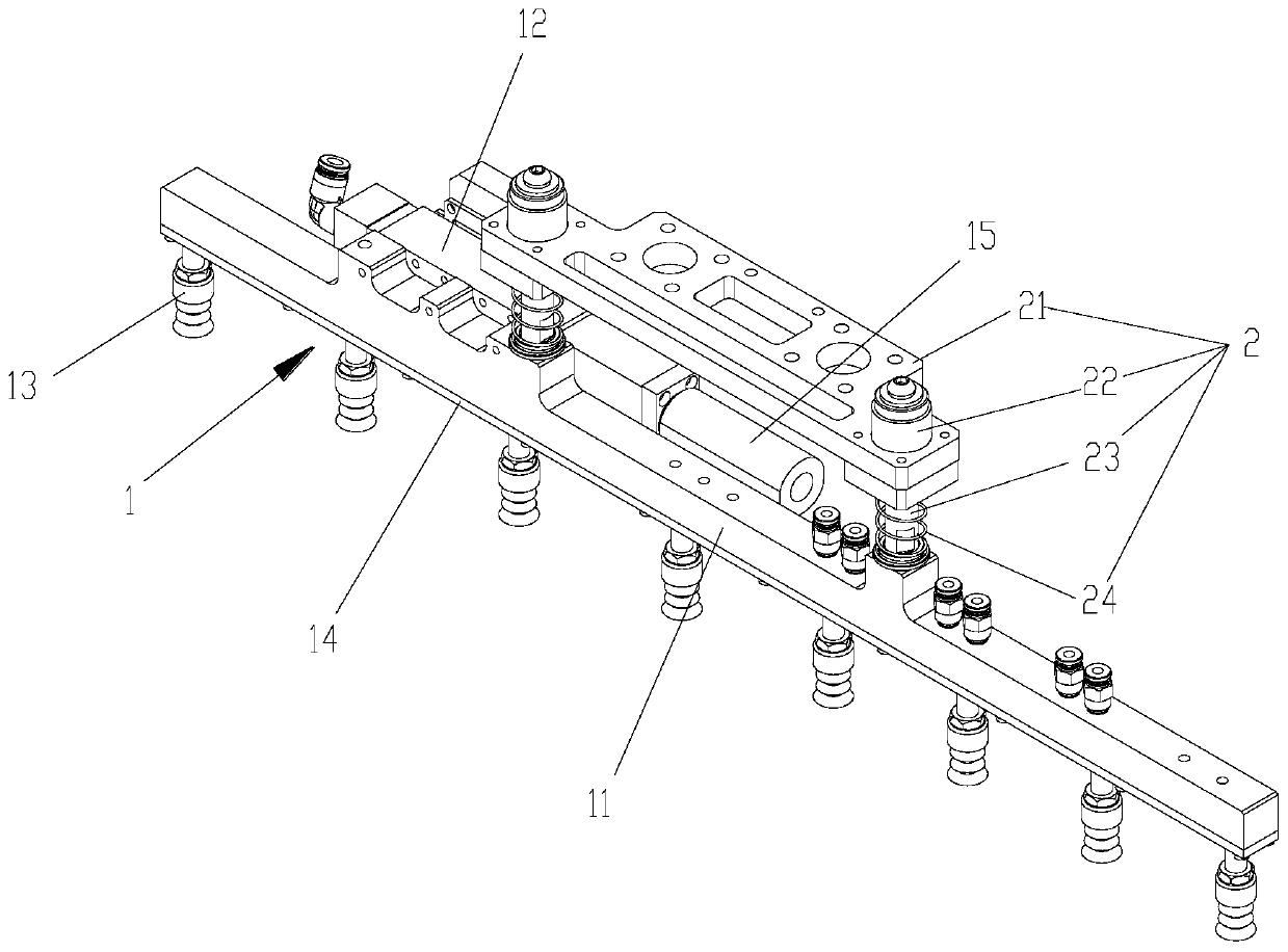
The invention discloses a clamp suction row and a transfer clamp of the same, wherein suction disks of the clamp suction row are communicated to a negative pressure cavity in a suction disk cavity body, so suction force of each of the suction disks is balanced; through further dismountable design of a baseplate, suction disks can be added easily, so the clamp suction row can be applicable to circuit boards with different sizes; a negative pressure generator is provided with a silencer for noise reduction; a damping device is disposed to avoid press damage on a circuit board; a first clamp suction row and a second clamp suction row with an adjustable distance are disposed on the clamp suction row and can be applicable to the circuit boards with different sizes, and a fixed third clamp suction row is disposed for enhancing stability of adsorption and grabbing; meanwhile, the first clamp suction row and the third clamp suction row can be further disposed into an installation structure which can be easily adjusted manually, so applicability of the clamp is enhanced; a U-shaped photoelectric switch, a metal detection sensor, a diffuse reflection photoelectric switch, an ultrasonic sensor and a lower probing sensor are disposed; and safety and accuracy in automatic control of the transfer clamp can be further enhanced.

Description

technical field [0001] The invention belongs to the technical field of circuit board fixtures, in particular to a fixture suction and discharge and its transfer fixture. Background technique [0002] In the field of circuit board inspection, the transfer fixture is a fixture used to grab the circuit board and move it; the suction and discharge of the fixture is set on the main body of the fixture of the transfer fixture to absorb the circuit board; the existing fixture suction and discharge and transfer fixture have the following features shortcoming: [0003] (1) The suction and discharge of the existing fixtures, the suction force of each suction cup is unbalanced. [0004] (2) It is inconvenient to add suction cups to the existing fixture suction and discharge. For circuit boards of different sizes and weights, the number of suction cups required is different. Firm; but the existing fixture suction and discharge is not convenient to add a suction cup. [0005] (3) When...

Claims


Application Information

Patent Timeline
IPC IPC(8): B65G47/91B65G43/00
CPCB65G43/00B65G47/912B65G2203/042
Inventor 陈右桃
Owner GUANGZHOU TAILI ELECTRICAL & MECHANICAL EQUIP CO LTD
Learn More