A structure and construction method of a combined girder bridge with external support girder type maintenance road

A girder bridge with external braced girders and construction method technology, which is applied to bridges, bridge construction, erection/assembly of bridges, etc., can solve problems such as increasing the difficulty of concrete pouring and hoisting, increasing the self-weight of bridge structures, and large structural dimensions of maintenance roads , to achieve the effect of shortening the construction period, reducing the cost of materials used, and improving construction efficiency

Active Publication Date: 2021-04-06
CHINA MAJOR BRIDGE ENERGINEERING
View PDF6 Cites 0 Cited by
  • Summary
  • Abstract
  • Description
  • Claims
  • Application Information

AI Technical Summary

Problems solved by technology

The maintenance road structure made of reinforced concrete is too large and heavy, which increases the difficulty of concrete pouring and hoisting during the construction period, and also easily increases the self-weight of the bridge structure and consumes materials

Method used


Image

  • A structure and construction method of a combined girder bridge with external support girder type maintenance road
  • A structure and construction method of a combined girder bridge with external support girder type maintenance road
  • A structure and construction method of a combined girder bridge with external support girder type maintenance road

Examples


Embodiment 1

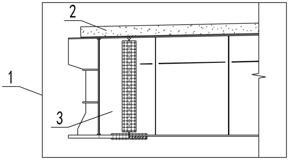
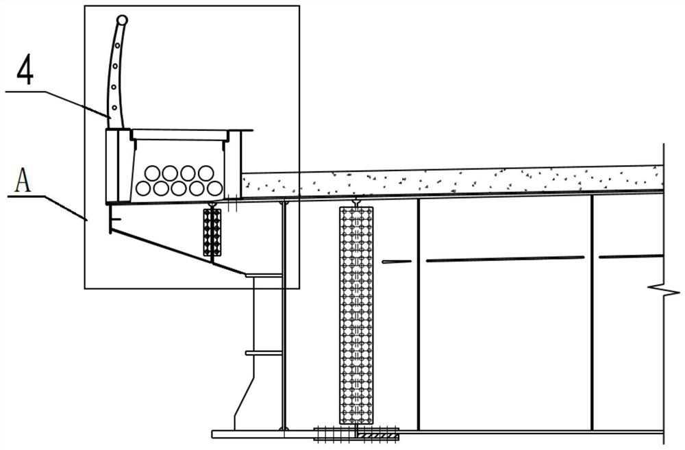
[0038] see Figure 1 to Figure 4 As shown, the embodiment of the present invention provides a combined girder bridge external support beam type inspection road structure, including:

[0039] The support beam 22 is fixedly connected to the left and right sides of the combined beam bridge 1 , the combined beam bridge 1 includes a steel beam 3 and a concrete bridge deck 2 , and the concrete bridge deck 2 is laid on the top of the steel beam 3 . This supporting beam 22 is provided with many, and many supporting beams 22 are connected with the steel girder 3 of combined beam bridge 1; The spacing is 3.5m.

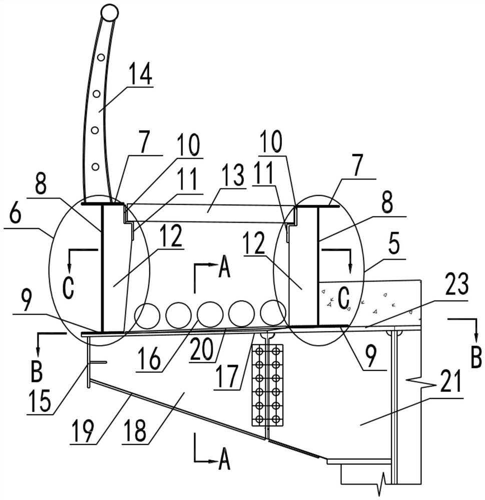
[0040] The support beam 22 comprises a support beam top plate 17, a support beam web 18 and a support beam bottom plate 19, the support beam top plate 17 is vertically connected to the top of the support beam web 18, and the support beam bottom plate 19 is vertically connected to the bottom of the support beam web 18. The support beam web 18 is a right-angled trapezoidal struc...

Embodiment 2

[0047] see image 3 As shown, the embodiment of the present invention provides a combined girder bridge with external support girder type inspection road structure. The difference between this embodiment and embodiment 1 is that: the first longitudinal beam 5 and the second longitudinal beam 6 are fixedly connected Beam vertical stiffener 12, the longitudinal beam vertical stiffener 12 on the first longitudinal beam 5 is located on the side close to the second longitudinal beam 6, the longitudinal beam vertical stiffener 12 on the second longitudinal beam 6 is located close to the first longitudinal beam 5 One side of the longitudinal beam vertical stiffener 12 is provided with a plurality of longitudinal beam vertical stiffeners 12 arranged at intervals along the length direction of the first longitudinal beam 5 and the second longitudinal beam 6 in an array, and the adjacent two longitudinal beam vertical The spacing between stiffening plates 12 is 0.5 m.

[0048] An L-shap...

Embodiment 3

[0050] see image 3 with Image 6 As shown, the embodiment of the present invention provides a combined girder bridge with external support girder type inspection road structure. The difference between this embodiment and embodiment 1 is that: the top of the support beam 22 is also equipped with a steel grating plate 20, and the steel grating The grid plate 20 is located between the first longitudinal beam 5 and the second longitudinal beam 6, and the steel grid plate has a hollow structure, which not only has high structural strength, but also has strong water permeability to prevent water accumulation. The steel grid plate 20 extends along the longitudinal bridge direction of the combined girder bridge 1 , and the access road plate 13 , the steel grid plate 20 , the first longitudinal beam 5 and the second longitudinal beam 6 form a closed long passageway. A bridge pipeline 16 is provided in the closed long channel enclosed by the inspection road slab 13, the steel grid pla...


PUM


Abstract

The invention discloses an externally supported girder type inspection road structure and a construction method of a combined girder bridge, and relates to the technical field of bridge construction. It includes: support beams, the support beams are fixedly connected on both sides of the combined beam bridge, there are multiple support beams, and the multiple support beams are arranged at intervals along the longitudinal direction of the combined beam bridge; the first longitudinal beam and the second longitudinal beam, the first The first longitudinal beam and the second longitudinal beam are fixedly arranged above the support beam at intervals, the first longitudinal beam is located on the side close to the combined beam bridge, and the second longitudinal beam is located on the side away from the combined beam bridge; Laying on the top of the first longitudinal girder and the second longitudinal girder, there are multiple access slabs, and the multiple access slabs extend along the longitudinal bridge direction of the combined girder bridge. The supporting beams, the first longitudinal beam and the second longitudinal beam of the external support beam type inspection road of the present invention are all made of steel structure materials, and the inspection road board adopts prefabricated slabs made of concrete materials, which can significantly reduce the structure The self-weight is lower, the cost of materials is reduced, and the construction is convenient.

Description

technical field [0001] The invention relates to the technical field of bridge construction, in particular to a structure and a construction method of an externally supported girder type maintenance road for a combined girder bridge. Background technique [0002] Combined girder bridge refers to a bridge structure in which two materials, concrete and steel, are used as the main beam section. Generally, the reinforced concrete bridge deck has the function of both the bridge deck and the combined beam compression flange, and at the same time is the longitudinal connection between the steel girders, which is conducive to improving the buckling capacity of the steel girders. Compared with concrete bridges, combined girder bridges have lighter weight and are suitable for use on poor foundations. At the same time, the steel girders of combined girder bridges are light in weight, simple in section, and easy to erect, and the steel girders can serve as supports during the concrete co...

Claims


Application Information

Patent Timeline
Patent Type & Authority Patents(China)
IPC IPC(8): E01D21/00
CPCE01D21/00
Inventor 张建强赵茜茜付岚岚万田保段雪炜张金涛唐斌孙建飞戴慧敏刘琳杰周银东汪奔唐超
Owner CHINA MAJOR BRIDGE ENERGINEERING
Why Eureka
Try Eureka