Triggering method based on I2S signal and oscilloscope

A signal and signal alignment technology, applied in the direction of instrument, digital variable display, digital variable/waveform display, etc., to achieve the effect of simple and efficient extraction operation, overcoming application limitations, and avoiding skew

Inactive Publication Date: 2020-02-04
SHENZHEN CITY SIGLENT TECH
View PDF6 Cites 5 Cited by
  • Summary
  • Abstract
  • Description
  • Claims
  • Application Information

AI Technical Summary

Problems solved by technology

[0005] The technical problem mainly solved by the present invention is how to overcome the application limitation that the existing oscilloscope cannot use the I2S signal for real-time triggering

Method used


Image

  • Triggering method based on I2S signal and oscilloscope
  • Triggering method based on I2S signal and oscilloscope
  • Triggering method based on I2S signal and oscilloscope

Examples


Embodiment 1

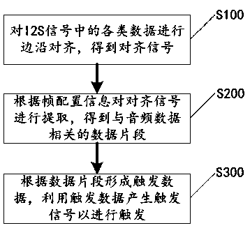
[0034] Please refer to figure 1 , the present application discloses a triggering method based on an I2S signal, which mainly includes steps S100-S300, which will be described respectively below.

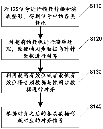
[0035] In step S100, timing alignment is performed on various types of data in the I2S signal to obtain an alignment signal. The I2S signal here includes frame synchronization data, clock data and audio data. Among them, the frame synchronization data is the data corresponding to LRCK after the digitization of the I2S signal, the clock data is the data corresponding to the BCK after the digitization of the I2S signal, and the audio data is corresponding to the DATA after the digitization of the I2S signal. The data.

[0036] It should be noted that when the I2S signal of analog audio is input into the oscilloscope, the attenuation of the signal will be different due to the different length of the signal path, and finally the three-way signal cannot be aligned in timing, resulting in...

Embodiment 2

[0079] Please refer to Figure 7 , the present application discloses an oscilloscope, which mainly includes a preprocessing unit 11, a buffer unit 12, a setting unit 13, a trigger unit 14 and an output unit 15, which will be described respectively below.

[0080] The pre-processing unit 11 is used for timing alignment of various types of data in the I2S signal and obtaining an alignment signal; the I2S signal here includes frame synchronization data, clock data and audio data. The pre-processing unit 11 can use a preset left-justified mode or a right-justified mode to perform timing alignment operations on various types of data in the I2S signal.

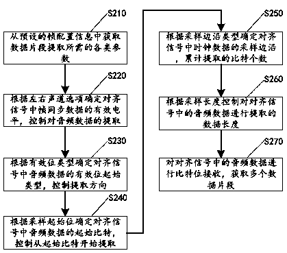
[0081] The buffer unit 12 is connected to the preprocessing unit 11, and is used to extract the alignment signal according to preset frame configuration information, obtain multiple data segments related to audio data in the alignment signal, and form trigger data according to the multiple data segments. Since multiple data segment...


PUM


Abstract

The invention discloses a triggering method based on an I2S signal and an oscilloscope. The triggering method comprises the steps of performing time sequence alignment on various data in the I2S signal to obtain an alignment signal, wherein the I2S signal comprises frame synchronization data, clock data and audio data; extracting the alignment signal according to preset frame configuration information to obtain a plurality of data fragments related to the audio data in the alignment signal; and forming triggering data according to the data fragments, and generating a triggering signal by utilizing the triggering data to perform triggering. According to the triggering method, the triggering signal is generated according to the I2S signal, so that a triggering event occurs after external triggering, the application limitation that the conventional oscilloscope cannot perform real-time triggering by utilizing the I2S signal is overcome, the triggering function of the oscilloscope is expanded, and an engineer can be helped to quickly analyze problems at multiple angles.

Description

technical field [0001] The invention relates to the technical field of oscilloscopes, in particular to an I2S signal-based trigger method and an oscilloscope. Background technique [0002] The rapid development and wide application of large-scale integrated circuits have greatly increased the complexity of digital systems, resulting in more and more complex design, development, testing and fault diagnosis. Intuitive analysis of the semaphore on the network, but the traditional limited trigger measurement method is far from meeting the needs of users. [0003] An oscilloscope can not only stably display repetitive periodic signals, but also display signals with specific characteristics. Its trigger sensitivity directly determines its ability to capture and display weak signals. Most of the existing trigger systems of digital oscilloscopes are analog trigger systems, and the comparators responsible for detecting signal levels use analog comparators that process the original m...

Claims


Application Information

Patent Timeline
IPC IPC(8): G01R13/02
CPCG01R13/029
Inventor 陈报吴乾科李振军
Owner SHENZHEN CITY SIGLENT TECH
Why Eureka
Try Eureka