Mixing device for potassium chlorate production

A technology of mixing device and potassium chlorate, which is applied to mixers with rotating stirring devices, mixers, transportation and packaging, etc., can solve the problems affecting the production efficiency of potassium chlorate and low feeding speed, and achieve good fixing effect and increase Productivity, effect of reducing cleaning time

Inactive Publication Date: 2020-02-07
LEIYANG JINYUE SCI & TECH DEV
View PDF6 Cites 1 Cited by
  • Summary
  • Abstract
  • Description
  • Claims
  • Application Information

AI Technical Summary

Problems solved by technology

The mixing device in the above patent requires manual feeding, resulting in low feeding speed and affecting the production efficiency of potassium chlorate

Method used


Image

  • Mixing device for potassium chlorate production
  • Mixing device for potassium chlorate production
  • Mixing device for potassium chlorate production

Examples


Embodiment 1

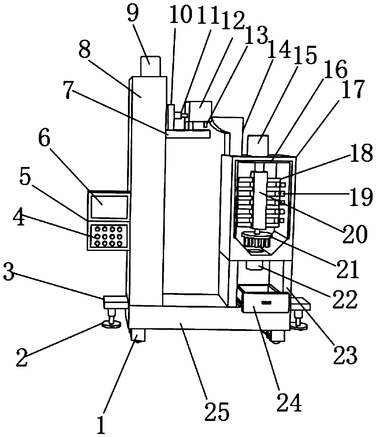
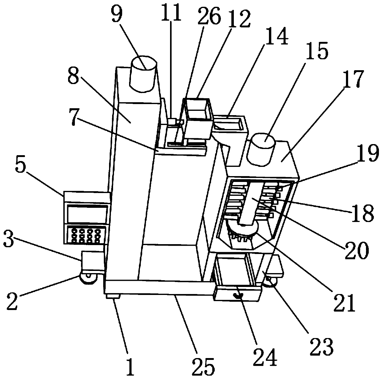
[0028] A kind of mixing device for potassium chlorate production, such as Figure 1-4 As shown, including the base 25, one side of the outer wall of the top of the base 25 is fixed with a support column 8 by screws, and one side of the outer wall of the support column 8 is provided with a groove, and the top outer wall of the support column 8 is fixed with a servo motor 9 by screws, and The output shaft of the servo motor 9 is connected with a screw mandrel 29 through a shaft coupling, the outer wall of the screw mandrel 29 is sleeved with a collar 28, and one side outer wall of the collar 28 is fixed with a moving plate 7 by screws, and the top outer wall of the moving plate 7 A chute 26 is provided, and the inwall of the chute 26 is slidably connected with a sliding column, the top of the sliding column is fixed with a feeding chute 12 by screws, and the bottom outer wall of the feeding chute 12 is provided with a feeding hole, and the inner wall of the feeding hole A feedin...

Embodiment 2

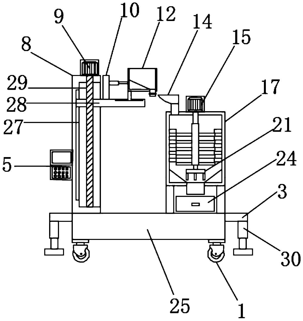
[0037] A kind of mixing device for potassium chlorate production, such as image 3 As shown, in order to solve the problem of stability in the mixing process; this embodiment makes the following improvements on the basis of embodiment 1: the outer walls on both sides of the base 25 are fixed with connecting plates 3 by screws, and the bottom outer walls of the connecting plates 3 pass through The screw is fixed with a hydraulic rod 30, and one end of the piston rod of the hydraulic rod 30 is fixed with a support plate 2 by a screw.

[0038] When this embodiment is in use, the hydraulic rod 30 is controlled to elongate the piston rod, and the support plate 2 contacts the ground to fix the device, which has a good fixing effect and improves the stability of the device during operation.


PUM


Abstract

The invention discloses a mixing device for potassium chlorate production, and relates to the technical field of chemical production. In order to solve the problems that the feeding speed is low and the production efficiency of potassium chlorate is influenced. The mixing device specifically comprises a base, wherein a supporting column is fixed on one side of the outer wall of the top of the basethrough screws; a groove is formed in the outer wall of one side of the supporting column; a servo motor is fixed on the outer wall of the top of the supporting column through screws; the output shaft of the servo motor is connected with a lead screw through a coupler; the outer wall of the lead screw is in cup joint with a lantern ring; a moving plate is fixed on the outer wall of one side of the lantern ring through screws; a sliding chute is formed in the outer wall of the top of the moving plate; the inner wall of the sliding chute is slidably connected with a sliding column; a feeding groove is fixed at the top end of the sliding column through screws; a feeding hole is formed in the outer wall of the bottom of the feeding groove; and a feeding pipe is inserted into the inner wall ofthe feeding hole. According to the mixing device, manual feeding is not needed, so that the feeding speed is high, and the production efficiency of potassium chlorate is improved.

Description

technical field [0001] The invention relates to the technical field of chemical production, in particular to a mixing device for potassium chlorate production. Background technique [0002] Potassium chlorate is colorless flaky crystal or white granule powder, salty and cool, strong oxidant. Stable at room temperature, it decomposes and releases oxygen above 400°C, and can form an explosive mixture when mixed with reducing agents, organic matter, combustibles such as sulfur, phosphorus or metal powder, and can explode when heated rapidly. Therefore, potassium chlorate is a highly sensitive explosive agent. If it is mixed with certain impurities, it will sometimes even explode under sunlight. It will explode in case of concentrated sulfuric acid. It can react with manganese dioxide as a catalyst to generate oxygen under heating conditions [0003] After retrieval, the patent of Chinese Patent Publication No. CN207478485U discloses a potassium chlorate mixer capable of effi...

Claims


Application Information

Patent Timeline
Patent Type & Authority Applications(China)
IPC IPC(8): B01F7/18B01F7/26B01F15/00B01F15/02B01F27/93
CPCB01F27/902B01F27/93B01F35/43B01F35/7173B01F35/71805
Inventor 周新红义训坤黄涛李泽龙
Owner LEIYANG JINYUE SCI & TECH DEV
Why Eureka
Try Eureka