Supercharge Your Innovation With Domain-Expert AI Agents!

Surface treatment device of satellite signal receiving equipment

A surface treatment device and receiving equipment technology, applied in the direction of spraying device, grinding drive device, metal processing equipment, etc., can solve the problems of high cost, weakened satellite signal, time-consuming and labor-intensive, etc., and achieve the effect of improving efficiency and improving the scope of application

Inactive Publication Date: 2020-02-07
浦江光特通讯技术有限公司
View PDF8 Cites 3 Cited by
  • Summary
  • Abstract
  • Description
  • Claims
  • Application Information

AI Technical Summary

Problems solved by technology

[0002] To receive satellite signals on the ground, a metal parabola, that is, a satellite pot, is generally used for reflection and reception. The satellite pot is used outdoors for a long time. Due to the influence of rain, air, and sunlight, the paint layer on the reflective surface of the satellite pot will gradually fall off and rust. It will affect the surface finish of the antenna, deteriorate the focusing effect, and weaken the received satellite signal. Traditionally, the derusting of satellite pots is generally done manually, which is time-consuming and laborious, and the efficiency is low. If there are a large number of satellite pots to be processed, manual processing Need cost is higher, in order to solve the above problem, proposed the present invention

Method used


Image

  • Surface treatment device of satellite signal receiving equipment
  • Surface treatment device of satellite signal receiving equipment
  • Surface treatment device of satellite signal receiving equipment

Examples


Embodiment Construction

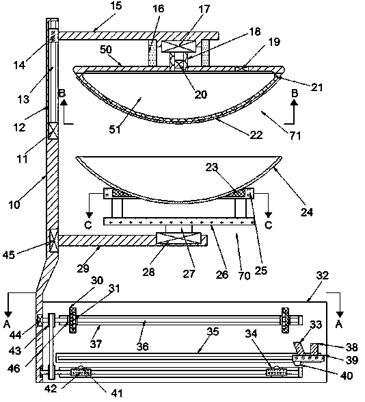
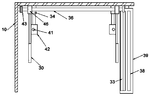
[0018] Combine below Figure 1-4 The present invention is described in detail, wherein, for the convenience of description, the orientations mentioned below are defined as follows: figure 1 The up, down, left, right, front and back directions of the projection relationship itself are the same.

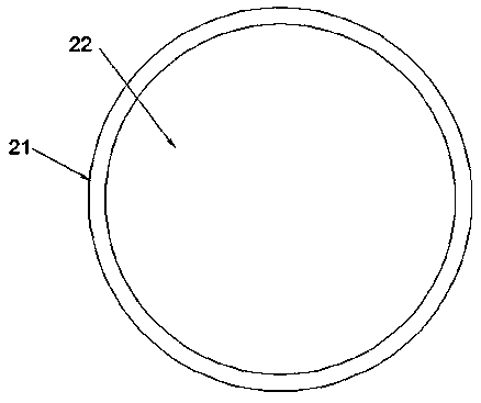
[0019] A surface treatment device for satellite signal receiving equipment described in conjunction with accompanying drawings 1-4, mainly includes a main support plate 10, the right end surface of the main support plate 10 is rotatably provided with a switching shaft 29, and the upper end surface of the switching shaft 29 is A rotating motor 28 is fixedly installed, and the upper end of the rotating motor 28 is dynamically connected with a rotating shaft 27. The upper end of the rotating shaft 27 is provided with a supporting mechanism 70. Before surface treatment, the satellite pan 24 is fixed by the supporting mechanism 70 and the The opening of the satellite pot 24 faces upwards; ...


PUM


Abstract

The invention discloses a surface treatment device of satellite signal receiving equipment. The surface treatment device comprises a main supporting plate, wherein a switching shaft is rotatably arranged on the right end surface of the main supporting plate; a rotating motor is fixedly arranged on the upper end surface of the switching shaft; the upper end of the rotating motor is in power connection with a rotating shaft; a supporting mechanism is arranged at the upper end of the rotating shaft; before surface treatment, a satellite pot is fixed through the supporting mechanism, and an opening of the satellite pot faces upwards; and a grinding mechanism comprising a composition plate is arranged on the upper side of the satellite pot. The satellite pot can be ground by using abrasive paper and is automatically painted after being grounded, so that the surface of the satellite pot is automatically treated; compared with manual treatment, the efficiency is improved; and meanwhile, the surface treatment device can be suitable for satellite pots with different diameters and in different sizes, and adjustment is not needed, so that the application range of the surface treatment deviceis greatly widened, and the surface treatment device can be used for large-batch recycling treatment of the satellite pots.

Description

technical field [0001] The invention relates to the technical field of satellite signal receiving equipment, in particular to a surface processing device for satellite signal receiving equipment. Background technique [0002] To receive satellite signals on the ground, a metal parabola, that is, a satellite pot, is generally used for reflection and reception. The satellite pot is used outdoors for a long time. Due to the influence of rain, air, and sunlight, the paint layer on the reflective surface of the satellite pot will gradually fall off and rust. It will affect the surface finish of the antenna, deteriorate the focusing effect, and weaken the received satellite signal. Traditionally, the derusting of satellite pots is generally done manually, which is time-consuming and laborious, and the efficiency is low. If there are a large number of satellite pots to be processed, manual processing Need cost is higher, in order to solve the above problem, propose the present inve...

Claims


Application Information

Patent Timeline
IPC IPC(8): B24B27/033B24B41/04B24B41/06B24B47/12B24B47/22B24B49/00B24B55/06B05B13/02
CPCB05B13/0278B24B27/033B24B41/04B24B41/061B24B47/12B24B47/22B24B49/00B24B55/06
Inventor 袁新芳
Owner 浦江光特通讯技术有限公司
Features
  • R&D
  • Intellectual Property
  • Life Sciences
  • Materials
  • Tech Scout
  • Unparalleled Data Quality
  • Higher Quality Content
  • 60% Fewer Hallucinations
Learn More