Adaptive continuously-adjustable cavitation device structure

An adaptive cavitator technology, applied in ships, special-purpose ships, underwater ships, etc., can solve problems such as the mismatch between the shape of the supercavitation and the shape of the sailing body, poor cavitation stability, and large overall resistance. The effect of continuous change satisfaction, reduction of frictional resistance, and reduction of total resistance

Active Publication Date: 2020-02-07
NAT UNIV OF DEFENSE TECH
View PDF11 Cites 13 Cited by
  • Summary
  • Abstract
  • Description
  • Claims
  • Application Information

AI Technical Summary

Problems solved by technology

[0009] The technical problem to be solved by the present invention is to provide an adaptive and continuously adjustable cavitator structure and underwater vehicle to solve the supercavitation generated by the current fixed structure cavitator during the acceleration process of the underwater vehicle The shape does not match the shape of the vehicle, the overall resistance is too large, the stability of the cavitation is poor, and the maneuverability is poor.

Method used


Image

  • Adaptive continuously-adjustable cavitation device structure
  • Adaptive continuously-adjustable cavitation device structure
  • Adaptive continuously-adjustable cavitation device structure

Examples


Embodiment 1

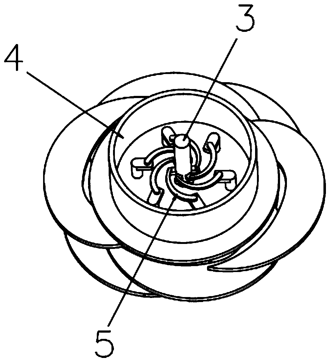
[0054] as attached Figure 2-Figure 4 An adaptive and continuously adjustable cavitator structure shown includes a reference chassis 4 connected to each other, a rotatable telescopic component and a drive mechanism component, wherein,

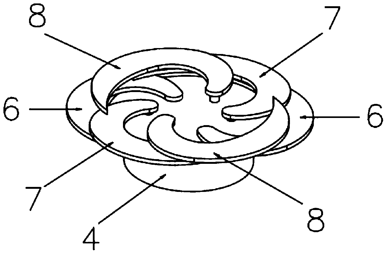
[0055] The reference chassis 4 is installed between the rotatable telescopic part and the drive mechanism part, the geometric center of the reference chassis 4 is fixedly connected to the drive mechanism part, and the outer surface is in contact with the innermost surface of the rotatable telescopic part; In this embodiment, the reference chassis 4 has a circular shape, also called a reference disk.

[0056] In another embodiment of the present invention, the shape of the reference chassis is conical or concave cone-shaped.

[0057] The rotatable telescopic component includes three layers of fan-shaped groups that can move synchronously inward / outward. Each layer of the fan-shaped group is respectively connected to the drive link 5, and the ot...

Embodiment 2

[0078] as attached Figure 2-Figure 9 The self-adaptive and continuously adjustable cavitator structure shown includes a reference chassis 4 connected to each other, a rotatable telescopic part and a drive mechanism part. The difference from Embodiment 1 is that the rotatable telescopic part includes n layers A set of sectors that are cross-mounted on the reference chassis 4 and can move synchronously inwardly / outwardly, where n is an integer greater than 3; the process and principle of use are the same as those in Embodiment 1.

Embodiment 3

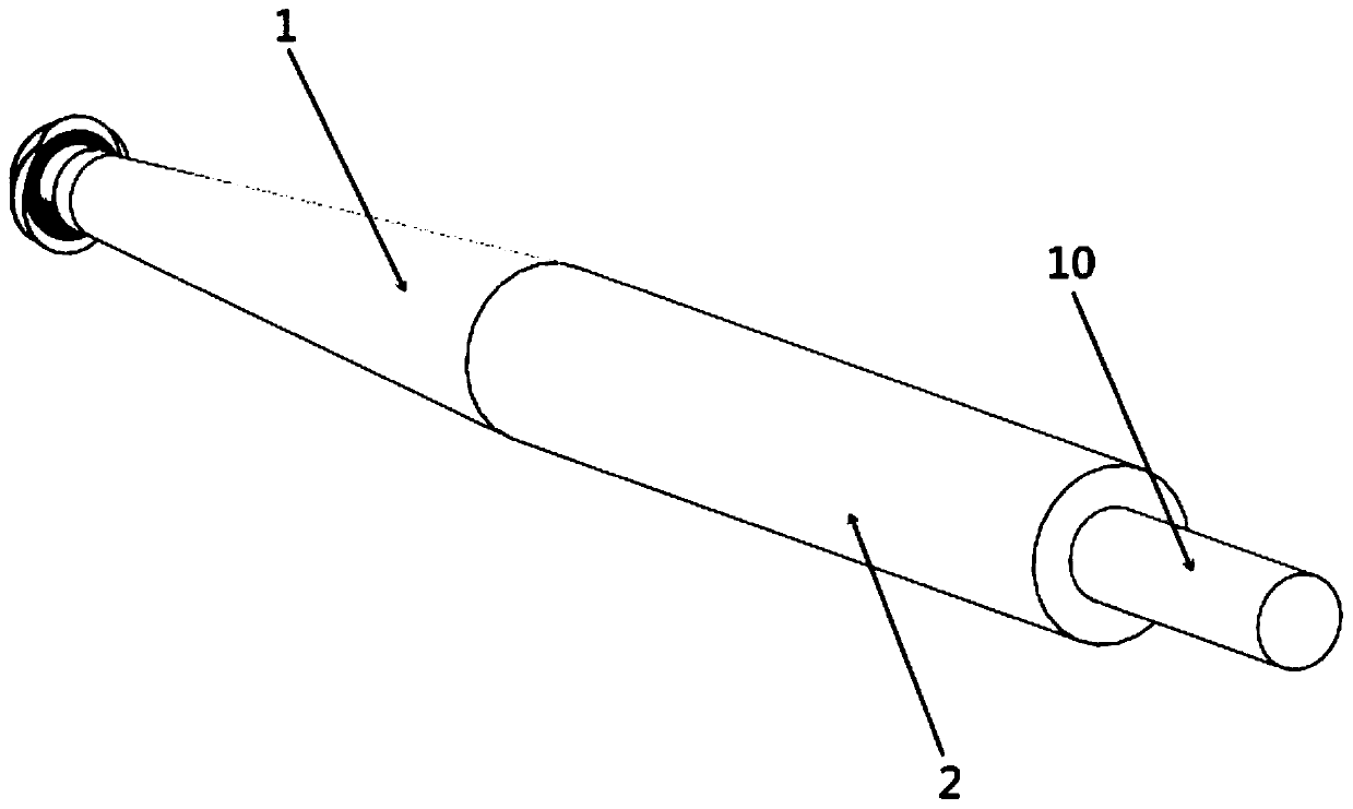
[0080] as attached figure 1 As shown in the underwater vehicle, the present invention also provides an underwater vehicle on the basis of Embodiment 1 or Embodiment 2, including the main body of the vehicle and the self-adaptive continuously adjustable The cavitator structure, the self-adaptive continuously adjustable cavitator structure is fixedly connected to the main body of the vehicle by welding, screwing or bonding, and the aircraft is coaxial with the reference chassis 4 .

[0081] Specifically, the main body of the navigation body includes a conical body 1 that is docked with the reference chassis 4 at one end and a cylindrical body 2 that is fixedly connected to the other end of the conical body 1. The cylindrical body 2 is far away from the One end of the conical projectile 1 is fixedly connected to the nozzle 10 of the navigation body; the reference chassis 4 is rigidly connected to the conical projectile 1; in this embodiment, the cylindrical body 2 is cylindrical;...


PUM


Abstract

The invention discloses an adaptive continuously-adjustable cavitation device structure. The adaptive continuously-adjustable cavitation device structure comprises a benchmark chassis, a rotatable telescopic assembly and a drive mechanism assembly which are connected with one another, wherein the benchmark chassis and the rotatable telescopic assembly rotate under the power drive action of a servomotor, and the diameter of an outer edge formed by multiple layers of sector part groups in rotating is continuously adjustable along with rotation changes of the servo motor. In the variable speed sailing process of an underwater sailing body, the adaptive continuously-adjustable cavitation device structure provides power through the drive mechanism assembly to drive the multiple layers of sector part groups of the rotatable telescopic assembly to synchronously expand outward or contract inward, and adjusts the drive mechanism assembly according to change situation feedback of hydrokinetic parameters of an external flow field of the sailing body so as to realize adaptive change of the diameter of a cavitation device, thereby completing control for the size and the form of vacuoles, decreasing the wetting area of the underwater sailing body and reducing pressure difference resistance additionally caused to the utmost, greatly reducing frictional resistance and total resistance, and greatly improving the maximum speed and sailing distance of the sailing body.

Description

technical field [0001] The invention relates to the field of cavitator structure design simulation in supercavitation technology, in particular to an adaptive and continuously adjustable cavitator structure under different cavitation numbers and an underwater vehicle equipped with the cavitator structure . Background technique [0002] The head of a supercavitating vehicle generally needs to be equipped with special components that are conducive to inducing cavitation, called cavitators. In order to enable the supercavitating vehicle to realize complex movements such as turning, floating, and variable speed during underwater operations, the variable structure cavitator located at the head plays a key role, and it should realize effective control of cavitation to meet The cavitation scale matches the vehicle body during full-speed variable-speed navigation, so that stable, efficient drag-reducing, and shape-controllable supercavitation can be generated. [0003] The shape o...

Claims


Application Information

Patent Timeline
Patent Type & Authority Applications(China)
IPC IPC(8): B63G8/00
CPCB63G8/00
Inventor 刘波周后村向敏谢泽阳张为华王东辉武泽平
Owner NAT UNIV OF DEFENSE TECH
Why Eureka
Try Eureka