Automatic oiling device for conveying chains of transverse moving rack

An automatic refueling and conveying chain technology, which is applied to transmission parts, escalators, transportation and packaging, etc., can solve the problems of large plate conveying chain, oil pollution on the lower surface of the steel plate, oil dripping and waste, etc., to improve friction conditions, Effect of reducing downtime and preventing fatigue fracture

Inactive Publication Date: 2020-02-07
BAOSHAN IRON & STEEL CO LTD
View PDF5 Cites 0 Cited by
  • Summary
  • Abstract
  • Description
  • Claims
  • Application Information

AI Technical Summary

Problems solved by technology

However, this device has relatively large limitations in use, because the device brushes lubricating oil onto the transmission chain of the escalator through the oil guide brush assembly, that is, the entire chain is all brushed with lubricating oil, and is limited to Where there is no special requirement for the oil receiving point
The reason why it is not suitable for the slab conveyor chain of the traversing platform is that the slab conveyor chain has a large volume, and it is strictly required that there is no oil stain on the panel, otherwise it will cause oil stain defects on the lower surface of the conveyed steel plate, and it is easy to use a brush to add oil. The panel is stained with oil
In addition, the refueling of the oil guide brush assembly is more suitable for chains with high speed and continuous operation. For the conveyor chain with frequent start and stop operations and low speed, it is easy to cause oil dripping and waste and pollute the environment.

Method used


Image

  • Automatic oiling device for conveying chains of transverse moving rack
  • Automatic oiling device for conveying chains of transverse moving rack
  • Automatic oiling device for conveying chains of transverse moving rack

Examples


Embodiment Construction

[0022] The technical solutions of the present invention will be further described below in conjunction with the accompanying drawings and embodiments.

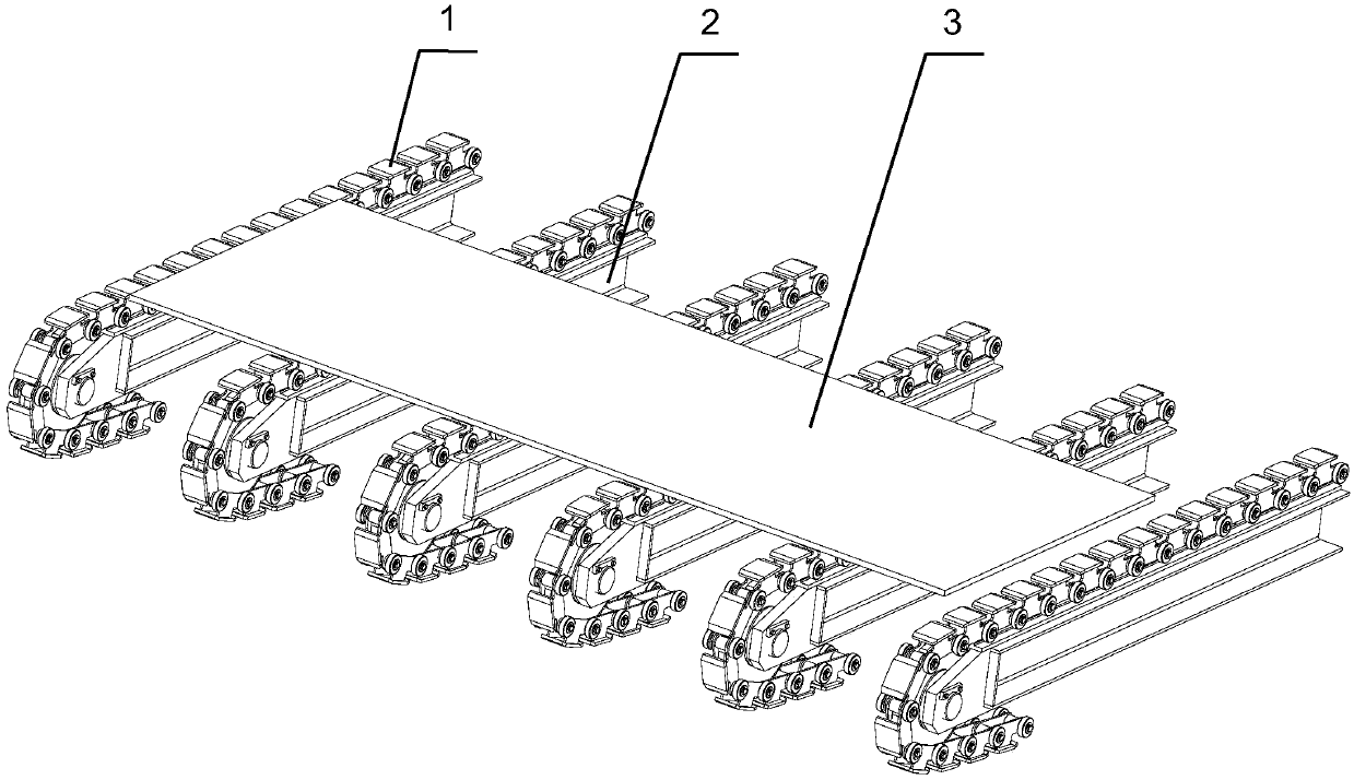
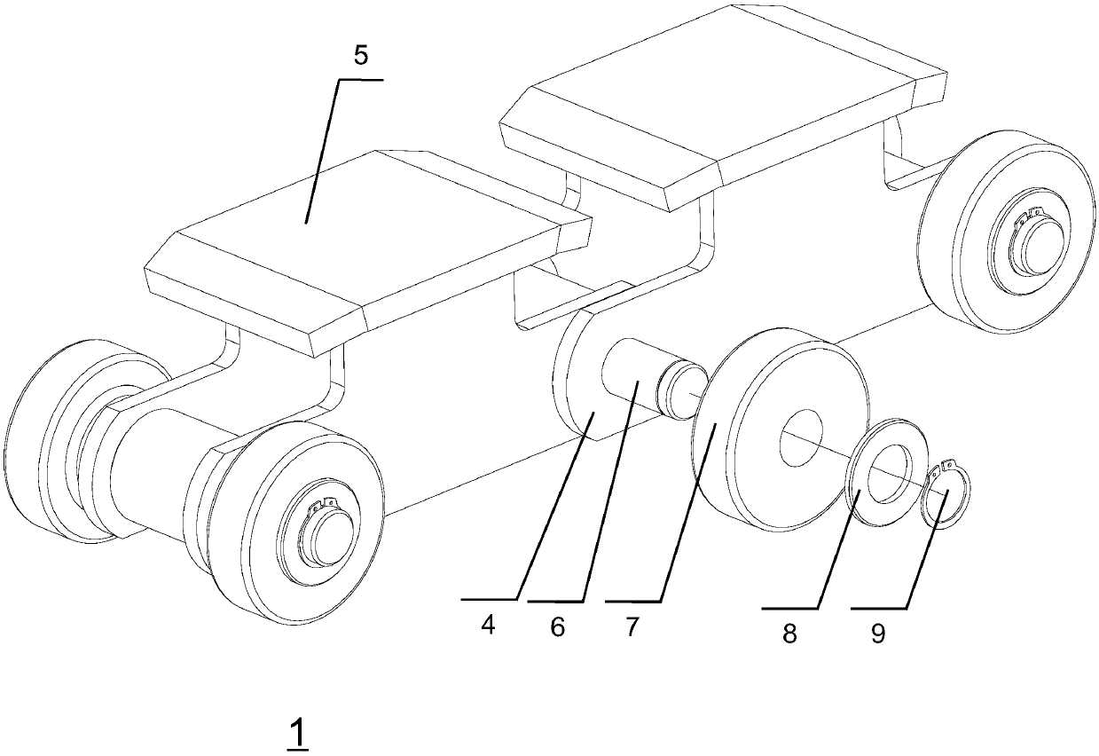
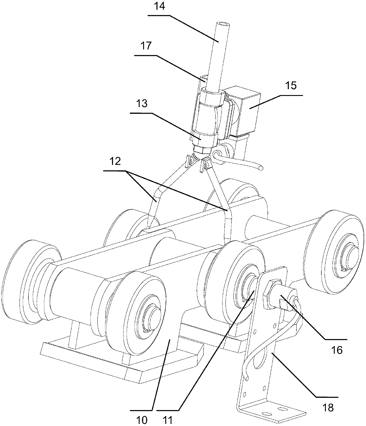
[0023] Please combine image 3 As shown, an automatic refueling device for a conveyor chain of a traversing platform provided by the present invention is provided on the tensioning sprocket fixing bracket of each conveyor chain, and the conveyor chain includes: a side chain plate 10, and is installed on The advantage of installing the roller shafts 11 on both sides of the side chain plate 10 at this position is that during the operation of the conveyor chain, the relative position of each chain is basically fixed, which is more suitable for the automatic oiling device of the present invention. . The automatic refueling device of the present invention comprises: several refueling mechanisms, and an electrical mechanism connected with the several refueling mechanisms, and the electric mechanism is used to control the several re...


PUM


Abstract

The invention discloses an automatic oiling device for conveying chains of a transverse moving rack. The device is arranged on a tension chain wheel fixing support of each conveying chain, and each conveying chain comprises a side chain plate and roller shafts arranged on the two sides of the side chain plate; the oiling device comprises a plurality of oiling mechanisms and an electrical mechanismconnected with the plurality of oiling mechanisms; the electrical mechanism is used for controlling the plurality of oiling mechanisms to carry out oiling operation on the conveying chains; each oiling mechanism comprises two oil dripping hard pipes, a three-way joint, an oil inlet pipeline, a normally-closed electromagnetic valve and a normally-opened proximity switch; and the electrical mechanism comprises a manual button switch, an automatic contact switch and a power-on delay relay. The oiling device is used for improving the friction conditions between rollers and the roller shafts, inhibiting generation of broken chains and reducing on-site noise.

Description

technical field [0001] The invention relates to steel plate conveying equipment in the metallurgical industry, and more specifically relates to an automatic refueling device for a conveying chain of a traversing rack. Background technique [0002] In the thick plate production line of the metallurgical industry, the traversing bench for conveying steel plates is widely used, such as inspection and grinding benches in the shear line area, traversing benches, finished product collection benches, and sample collection benches. [0003] The existing traversing platform structure such as figure 1 As shown, the conveyor chain 1 lies on the guide rail 2 to form a revolving mechanism that can be turned forward and reverse. The mechanism is arranged at equal intervals horizontally to form a platform. The motor under the platform is driven to realize the 3-point lateral movement of the steel plate. [0004] The composition structure of conveyor chain 1 is as follows: figure 2 As s...

Claims


Application Information

Patent Timeline
Patent Type & Authority Applications(China)
IPC IPC(8): B66B31/00F16H57/05
CPCB66B31/00F16H57/05
Inventor 朱剑恩丁海绍沈大良
Owner BAOSHAN IRON & STEEL CO LTD
Why Eureka
Try Eureka