Self-anchorage type suspension bridge design and construction method adopting first cable later beam dynasty

A technology of self-anchored suspension bridge and construction method, applied in the direction of suspension bridge, bridge form, bridge construction, etc., can solve the problem of increasing the span of self-anchored suspension bridge, and achieve the effect of improving competitiveness, clear force and easy monitoring

Inactive Publication Date: 2020-02-07
ZHEJIANG PROVINCIAL INST OF COMM PLANNING DESIGN & RES CO LTD
View PDF8 Cites 11 Cited by
  • Summary
  • Abstract
  • Description
  • Claims
  • Application Information

AI Technical Summary

Problems solved by technology

[0007] The Chinese patents whose publication numbers are CN106149569A, CN204418031U and CN104652285A propose to adopt a tower-beam temporary anchorage device, and the temporary anchorage device is used to bear the horizontal force component of the main cable in the construction process; but as the span of the self-anchored suspension bridge continues to increase, The horizontal component force of the main cable is also continuously increasing, the temporary consolidation between the main girder and the pier tower and the thrust stiffness of the pier tower itself limit the further increase of the span of the self-anchored suspension bridge

Method used


Image

  • Self-anchorage type suspension bridge design and construction method adopting first cable later beam dynasty
  • Self-anchorage type suspension bridge design and construction method adopting first cable later beam dynasty
  • Self-anchorage type suspension bridge design and construction method adopting first cable later beam dynasty

Examples


Embodiment Construction

[0034] In order to describe the present invention more specifically, the technical solutions of the present invention will be described in detail below in conjunction with the accompanying drawings and specific embodiments.

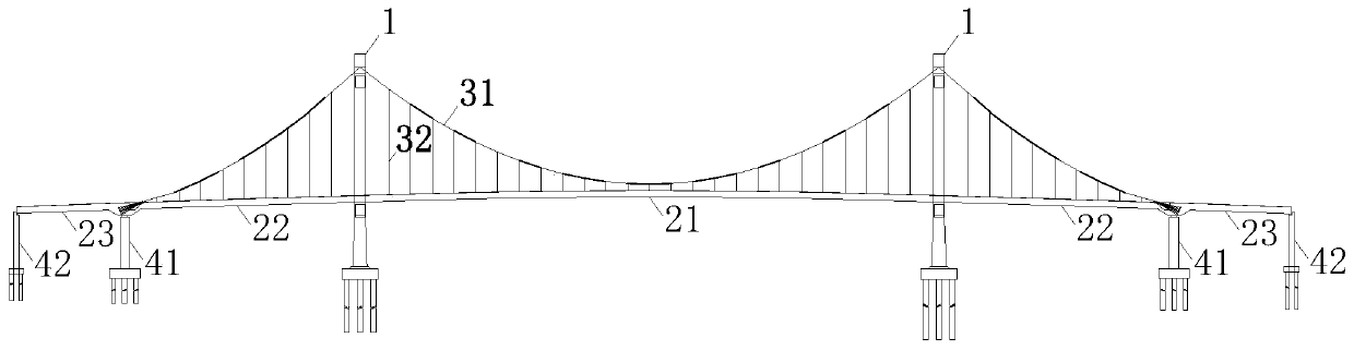
[0035] like figure 1 As shown, it is a typical self-anchored suspension bridge with two towers and five spans. 22 and anchor span girder 23), main cable 31 and sling 32 etc.

[0036] from figure 1 The self-anchored suspension bridge is in a reasonable bridge state. It can be seen that since the main cable 31 of the self-anchored suspension bridge is anchored on the main girder, when the main girder acts on the vertical load, the main cable 31 has a large horizontal component force. The component force will be borne by the main girder. The state of the structure during the construction process is not exactly the same as that of the completed bridge. During the construction process, the main girder is assembled in sections; It is also one of the design ...


PUM


Abstract

The invention discloses a self-anchorage type suspension bridge design and construction method adopting a first cable later beam dynasty. The method includes the steps that (1), bridge towers and piers are constructed, and main beam anchoring sections are constructed; (2), temporary anchors are constructed, and temporary pintle cables are mounted; (3), main cables are erected, and the temporary pintle cables are tensioned synchronously; (4), main beam sections are hoisted, main cable saddles on the tops of the bridge towers are pushed, and the temporary pintle cables are tensioned; and (5), the main beams are formed into a whole, the temporary pintle cables are detached, and system conversion is completed. The method has the beneficial effects that force bearing is clear, monitoring is facilitated, and navigation below a bridge is not interrupted, the construction method is simple and convenient, and design and monitoring are facilitated. Compared with a construction method adopting afirst beam later cable construction method, the requirements of navigation below the bridge can be guaranteed, the temporary measures that full framing and temporary piers are erected in a riverway with a deep riverbed are avoided, the construction problems of a self-anchorage type suspension bridge which has high requirements on navigation below the bridge and is located at the deep position of the riverbed can be solved, and the competitiveness of the large-span self-anchorage type suspension bridge is further improved.

Description

technical field [0001] The invention belongs to the technical field of bridge design and construction, and in particular relates to a design and construction method of a self-anchored suspension bridge with cables first and beams second. Background technique [0002] The biggest difference between the self-anchored suspension bridge and the traditional ground-anchored suspension bridge is that the main cable of the former is anchored on the main girder, while the main cable of the latter is anchored on the ground. Since the main cable of the self-anchored suspension bridge is anchored on the main girder, the main girder is subject to a huge horizontal component force after the bridge is completed; the main girder is gradually assembled into a whole during the construction process, and only when the main girder is integrated can it bear large Therefore, how to transfer the horizontal force of the main cable to the main girder has become one of the key technologies in the desi...

Claims


Application Information

Patent Timeline
Patent Type & Authority Applications(China)
IPC IPC(8): E01D11/02E01D21/00
CPCE01D11/02E01D21/00
Inventor 沈佳伟尹冉崔正春刘德宝张红星陈文敏黄鑫王巍吴文清王亮东郭万中游川李晓峰肖洒朱恩钱
Owner ZHEJIANG PROVINCIAL INST OF COMM PLANNING DESIGN & RES CO LTD
Why Eureka
Try Eureka