Roller type kinetic energy converter

A conversion machine, drum type technology, applied in the direction of reaction engine, engine components, machine/engine, etc., can solve the problems of reduced kinetic energy loss, complex structure, low kinetic energy conversion efficiency, etc., to achieve reduced kinetic energy loss, simple equipment structure, The effect of improving kinetic energy conversion efficiency

Pending Publication Date: 2020-02-07
大连宏立新能源科技有限公司
View PDF0 Cites 0 Cited by
  • Summary
  • Abstract
  • Description
  • Claims
  • Application Information

AI Technical Summary

Problems solved by technology

[0004] In order to overcome the shortcomings of large energy loss, low kinetic energy conversion efficiency, and complex structure in the existing water kinetic energy conversion equipment technology, the invention provides a drum type kinetic energy conversion machine, which makes the thrust direction of the water flow consistent with the rotation direction of the flow plate and the rotor The direction of rotation is the same, the front plate is fully stressed, the kinetic energy loss is greatly reduced, the kinetic energy conversion efficiency is greatly improved, and the equipment structure is relatively simple

Method used


Image

  • Roller type kinetic energy converter
  • Roller type kinetic energy converter
  • Roller type kinetic energy converter

Examples


Embodiment 1

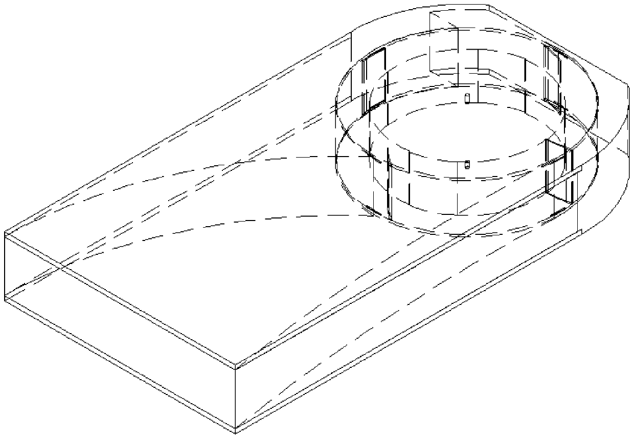
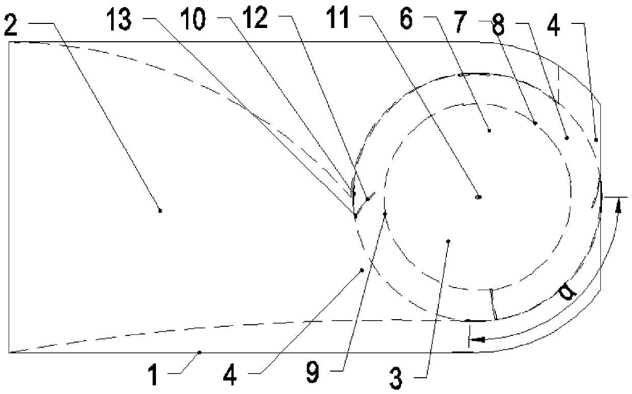
[0041] The utility model relates to a one-way drum type kinetic energy conversion machine.

[0042] The one-way drum type kinetic energy conversion machine is suitable for the kinetic energy conversion of one-way water flow, for example, it is suitable for installation in rivers, reservoirs and sea current environments with one-way flow in the ocean. At present, the world's largest ocean current energy generator has an installed capacity of 3.4 megawatts. According to preliminary calculations, the installed capacity of a single unit of the present invention can reach more than 10 megawatts in an ocean current environment; in the environment of rivers and reservoirs, the installed capacity of a single unit can be even larger.

[0043] like figure 1 , figure 2 As shown, the one-way kinetic energy conversion machine includes a casing 1 and a rotor 6 . like Figure 7 , Figure 8 As shown, the internal structure of the housing 1 includes the diversion channel 2 and the rotor ...
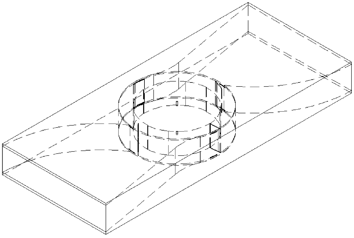
Embodiment 2

[0053] A two-way drum type kinetic energy conversion machine.

[0054] In the ocean, the existing sea (water) flow energy conversion equipment that utilizes ocean current energy to generate electricity, in addition to large energy loss, low kinetic energy conversion efficiency, and complex equipment structure, also has defects such as difficult installation and small installed capacity of a single machine. For this reason, the present invention has also designed a kind of two-way drum type kinetic energy conversion machine. In the environment of ocean tidal flow, according to the characteristic that the direction of tidal flow changes regularly in opposite directions, the bidirectional drum type kinetic energy conversion machine can receive the kinetic energy of sea (water) flow from two opposite directions for conversion. At present, the installed capacity of the world's largest ocean current energy generator is 3.4 MW. According to preliminary calculations, in the current e...


PUM


Abstract

The invention relates to water current kinetic energy conversion equipment, in particular to a roller type kinetic energy converter. A rotor of the converter is mounted on an outer shell through a rotor shaft, and the rotor is vertically mounted in a rotor bin. Incident flow plates are connected with the edges of rotor outer plates at the upper end and the lower end of the rotor, and the incidentflow plates are vertically mounted between the upper rotor outer plate and the lower rotor outer plate. The roller type kinetic energy converter is provided in order to overcome the defects that in the existing water current kinetic energy conversion equipment technology, energy losses are large, the kinetic energy conversion efficiency is low, the structure is complex, the equipment mounting difficulty is high, and the single-machine installed capacity is small, the thrust direction of water currents is consistent with the rotating direction of the rotor, the incident flow plates bear force comprehensively, the kinetic energy losses are greatly reduced, the kinetic energy conversion efficiency is greatly improved, the structure of the equipment is relatively simple, the mounting difficulty is greatly reduced, and the single-machine installed capacity is greatly increased.

Description

technical field [0001] The invention relates to a water kinetic energy conversion device, in particular to a drum type kinetic energy conversion machine. Background technique [0002] The existing kinetic energy conversion equipment that utilizes water flow energy to generate electricity is all vortex (blade) wheel type water flow energy conversion equipment, and its principle is basically the same as that of wind energy conversion equipment for wind power generation. The direction is vertical, the blades receive the thrust of the water flow at a certain angle, the effective force-bearing area is small, the energy loss is large, and there are disadvantages such as low kinetic energy conversion efficiency and complex equipment structure. Contents of the invention [0003] Purpose of the invention: [0004] In order to overcome the shortcomings of large energy loss, low kinetic energy conversion efficiency, and complex structure in the existing water kinetic energy conversi...

Claims


Application Information

Patent Timeline
Patent Type & Authority Applications(China)
IPC IPC(8): F03B3/14F03B3/16F03B13/26F03B17/06F03B13/08
CPCF03B3/14F03B3/16F03B13/08F03B13/264F03B17/06Y02E10/20
Inventor 邴振仁
Owner 大连宏立新能源科技有限公司
Why Eureka
Try Eureka