Method for improving dynamic range of photomultiplier

A photomultiplier tube and dynamic range technology, applied in the direction of dynamic electron multiplier tubes, etc., can solve the problems that the output signal of the anode of the device deviates from the linear working area saturation, and the total number of electron multiplications is too large, so as to improve the working dynamic range, broad market prospects, The effect of high application value

Active Publication Date: 2020-02-07
西安中科英威特光电技术有限公司
View PDF6 Cites 2 Cited by
  • Summary
  • Abstract
  • Description
  • Claims
  • Application Information

AI Technical Summary

Problems solved by technology

[0008] The invention provides a method for improving the dynamic range of photomultiplier tubes, which solves the problem that the current photomultiplier tubes have too large a total number of electron multiplications in the working

Method used


Image

  • Method for improving dynamic range of photomultiplier
  • Method for improving dynamic range of photomultiplier
  • Method for improving dynamic range of photomultiplier

Examples


Embodiment Construction

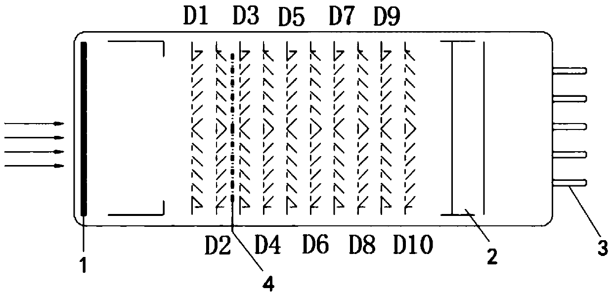
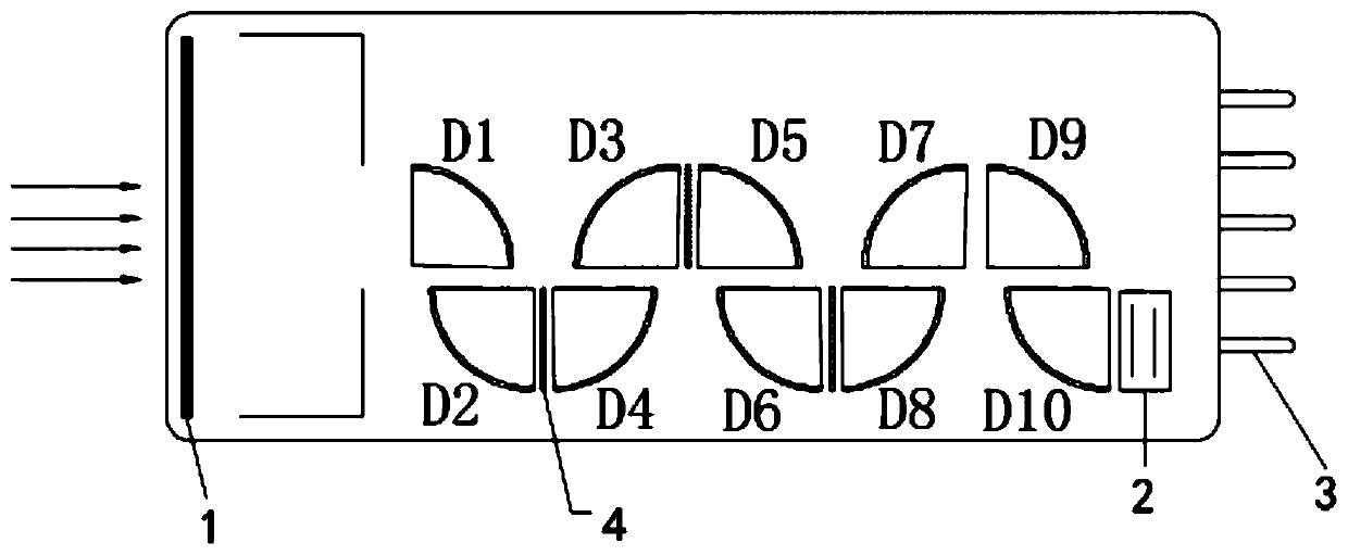
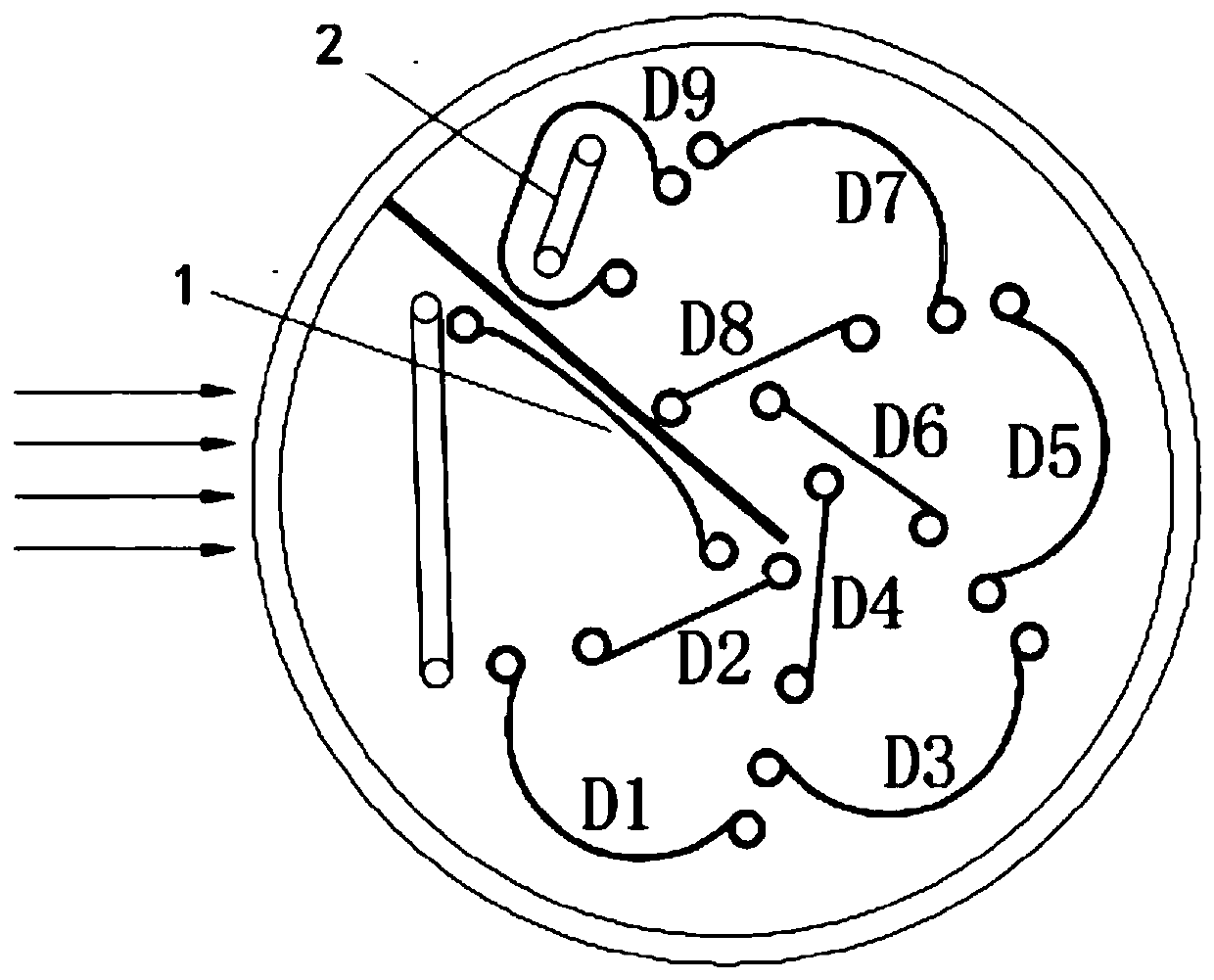
[0032] Attached below Figure 1-5 , the specific implementation of the present invention will be described in detail, but it should be understood that the protection scope of the present invention is not limited by the specific implementation.

[0033] The reason why the photomultiplier tube has excellent high current amplification and high signal-to-noise ratio, that is, high gain, benefits from the use of a secondary electron emission system based on multiple arrangements, that is, an electron multiplication system. Each dynode is a secondary electron multiplication system. The material composition has the ability to multiply the primary electrons, and the multiplication system is the most critical part that determines the sensitivity of the whole tube. It can multiply electrons under low-noise conditions. The electron multiplication system generally consists of several to 15 levels. There are two types of focused and non-focused types. Focused dynodes have ring tile multipl...


PUM


Abstract

The invention relates to the technical field of photomultipliers, and provides a method for improving the dynamic range of a photomultiplier so as to solve the problem that when an existing photomultiplier detects strong light signals, the dynamic range of a device is limited due to the fact that the number of multiplied electrons is too large. When the photomultiplier detects a strong light signal, cathode current or dynode current of the photomultiplier is greater than a set trigger threshold, and the working voltage of a dynode system or a modulation electrode is subjected to linkage adjustment, so that the number of electrons entering a subsequent dynode is reduced or the energy is reduced, and the whole photomultiplier works in a linear working region. The method for improving the dynamic range of the photomultiplier makes the photomultiplier better adapt to the change of light signal intensity, and the dynamic range of a common photomultiplier can be increased by 2-10 times or even higher on the original basis.

Description

technical field [0001] The invention relates to the technical field of photomultiplier tubes, in particular to a method for improving the dynamic range of photomultiplier tubes. Background technique [0002] A photomultiplier tube (PMT for short) is an electric vacuum photodetection device, mainly composed of a light window, a photocathode, an electron multiplication system and an anode. Its working principle is that the weak optical signal emitted by the detection target is incident on the photocathode through the light window, and the electrons of the photocathode are converted into space electron beam signals through the photoelectric effect and emitted into the vacuum, and then the electrons are multiplied by electric field acceleration and electron optical focusing. The system, after N-level multiplication, amplifies the electron beam signal N times and outputs it, and finally collects it by the anode to form the anode photocurrent and the signal voltage on the load, so...

Claims


Application Information

Patent Timeline
IPC IPC(8): H01J25/76
CPCH01J25/76
Inventor 李赟
Owner 西安中科英威特光电技术有限公司
Why Eureka
Try Eureka