
Cavity filter cover board

A cavity filter and cover plate technology, applied in the field of signal processing, can solve the problems of increasing the number of filter parts and production processes, increasing the internal loss of resonators, increasing manufacturing costs, etc., achieving simple structure, reducing vibration, and improving efficiency Effect

Pending Publication Date: 2020-02-07
苏州爱超诺智能自动化有限公司
View PDF0 Cites 2 Cited by
  • Summary
  • Abstract
  • Description
  • Claims
  • Application Information

AI Technical Summary

Problems solved by technology

[0003] In the traditional technology, the metal tuning screw set in the case cover is usually used as an adjustment part of the resonator. When the tuning screw is rotated, the distance between it and the internal conductor of the resonator changes, thereby changing the internal conductor and the resonator case cover. However, when using the tuning screw to adjust the frequency, the number of filter parts and production steps are increased, which increases the manufacturing cost, and the electrical contacts in the threads will deteriorate over time, causing tuning changes, increasing The internal loss of the resonator, and if the tip of the tuning screw is close to the end of the internal conductor in a high-capacity filter, it will break

Method used


Image

  • Cavity filter cover board
  • Cavity filter cover board
  • Cavity filter cover board

Examples


Embodiment Construction

[0021] The following will clearly and completely describe the technical solutions in the embodiments of the present invention with reference to the accompanying drawings in the embodiments of the present invention. Obviously, the described embodiments are only some, not all, embodiments of the present invention. Based on the embodiments of the present invention, all other embodiments obtained by persons of ordinary skill in the art without making creative efforts belong to the protection scope of the present invention.

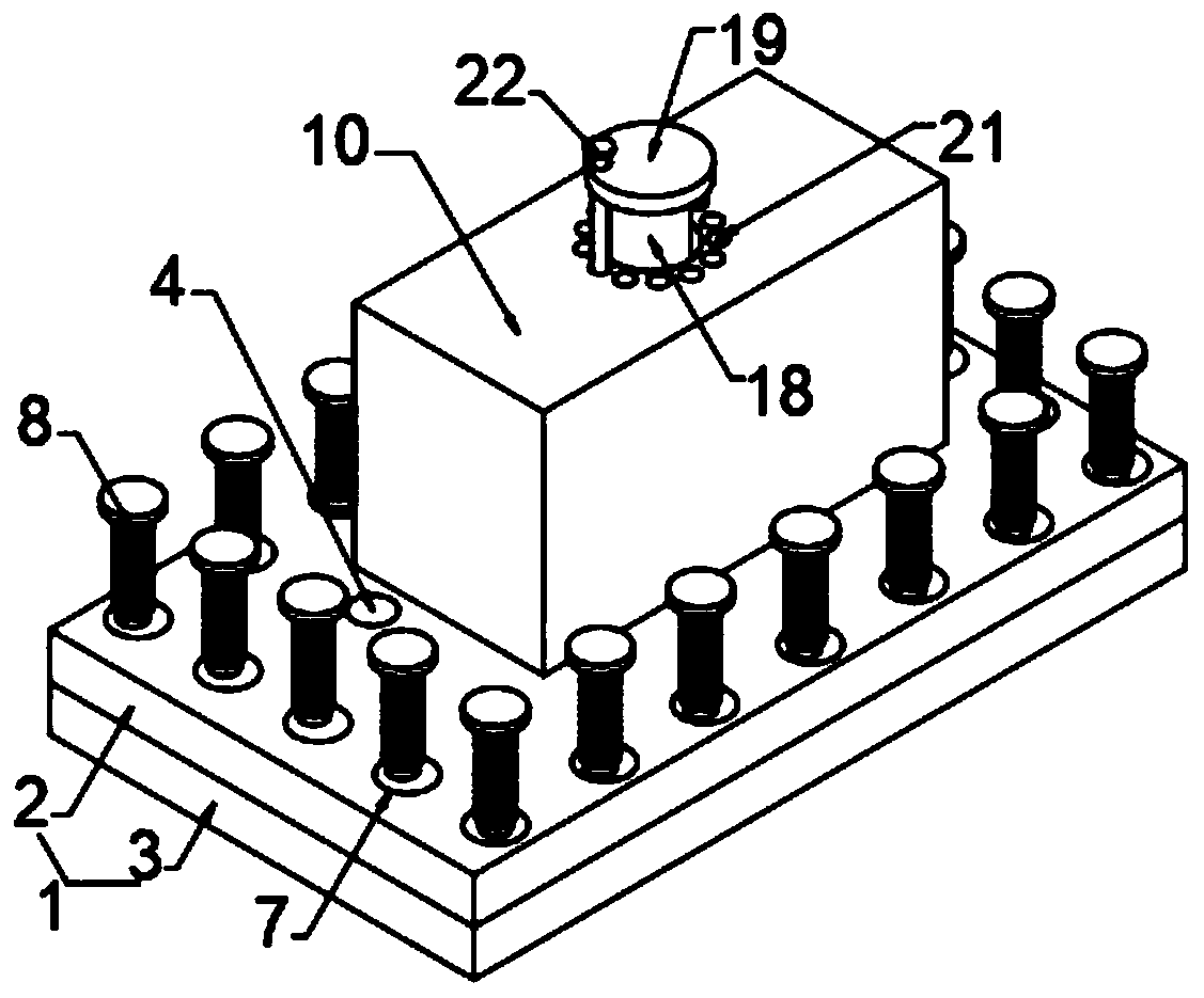
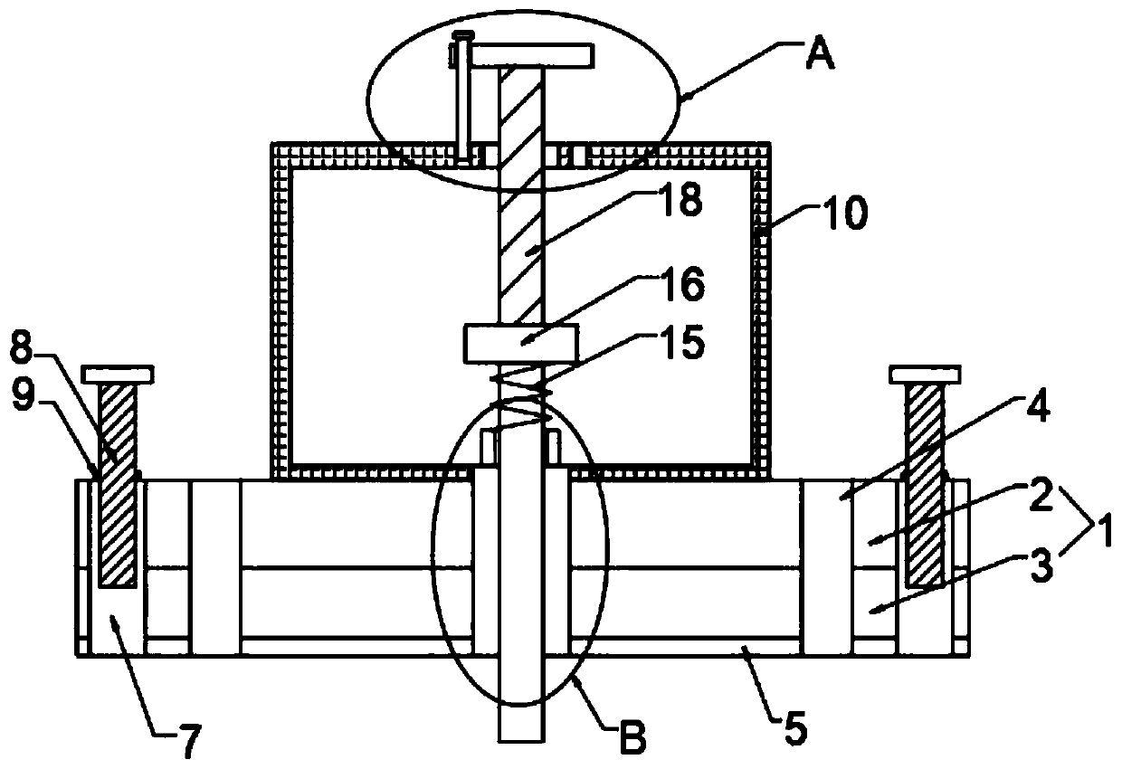
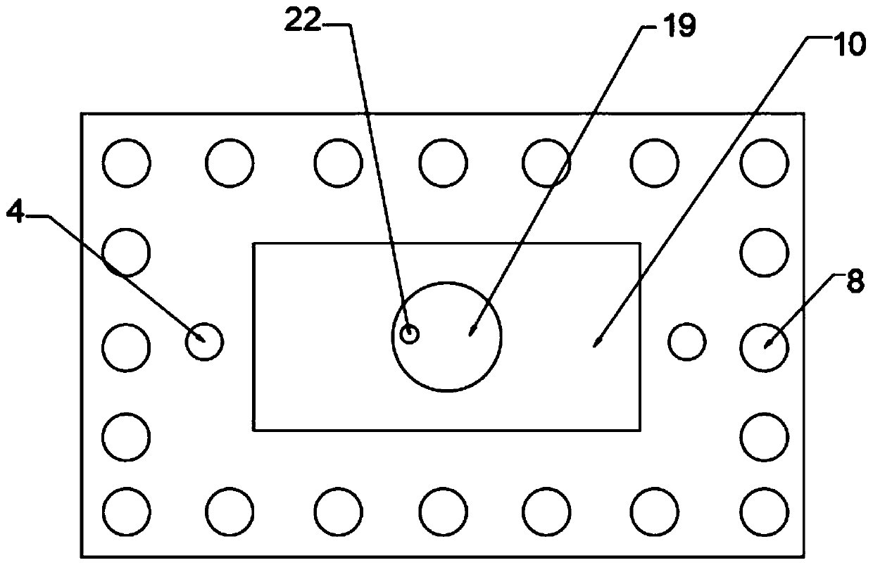
[0022] The present invention provides such as Figure 1-5 The shown cavity filter cover plate includes a plate body 1, the material of the plate body 1 is copper aluminum alloy, that is, one side is made of copper material, and the other side is made of aluminum material, and the upper surface of the plate body 1 is fixedly connected with a square box 10. The inside of the square box body 10 is provided with a frequency adjustment mechanism, and a frequency ad...


PUM


Abstract

The invention discloses a cavity filter cover board, and relates to the technical field of signal processing. The cavity filter cover board comprises a board body. The upper surface of the board bodyis fixedly connected with a square box body; a frequency adjusting mechanism is arranged in the square box body; the frequency adjusting mechanism comprises a debugging rod; a first through hole matched with the debugging rod is formed in the bottom of the square box body; a second through hole is formed in the middle of the upper surface of the board body; one end of the debugging rod runs through the first through hole and the second through hole and extends to one side of the board body; a connecting block is fixedly connected to the bottom of an inner cavity of the square box body; a thirdthrough hole is formed in the middle of the connecting block; an insulating spring is fixedly connected to the top of the connecting block; a moving board is fixedly connected to the top end of the insulating spring; and the other end of the debugging rod is fixedly connected with the bottom of the moving board. According to the invention, through the square box body and the frequency adjusting mechanism arranged in the square box body, the frequency of the cavity filter can be adjusted more conveniently, the frequency modulation efficiency is improved, and the working efficiency is improved.

Description

technical field [0001] The invention relates to the technical field of signal processing, in particular to a cavity filter cover plate. Background technique [0002] As the name implies, the filter is to filter the electromagnetic wave signal, let the required signal pass through, and suppress the unnecessary signal. The main purpose is to solve the interference problem between different frequency bands and different forms of wireless communication systems. Insertion loss, in-band fluctuation, out-of-band rejection, port standing wave ratio, isolation, square coefficient, power capacity, group delay index to describe, the cavity filter is a kind of microwave filter, and the cavity filter According to its different states, it can be divided into comb coaxial filter, dielectric filter, waveguide filter and helical filter. The cavity filter is cut from metal as a whole and has a firm structure. Strong, the cavity filter has a good frequency selective filtering effect in circui...

Claims


Application Information

Patent Timeline
Patent Type & Authority Applications(China)
IPC IPC(8): H01P1/207
CPCH01P1/207
Inventor 姜卫清
Owner 苏州爱超诺智能自动化有限公司
Learn More