Handle for moving trolley of surgical robot

A technology of surgical robot and mobile trolley, which is applied in the field of the handle of the surgical robot mobile trolley, which can solve the problems of inconvenient pushing in reverse, occupation of work space, and inconvenience of surgical staff, so as to achieve simple and convenient operation, easy forward and backward, and convenient The effect of using

Active Publication Date: 2020-02-11
杭州唯精医疗机器人有限公司
View PDF23 Cites 1 Cited by
  • Summary
  • Abstract
  • Description
  • Claims
  • Application Information

AI Technical Summary

Problems solved by technology

[0005] The purpose of the present invention is to solve the problem that the handle of the existing mobile trolley for surgical robots is very inconvenient for reverse pushing due to the fixed position of the components, and the When moving to the designated position, the handle assembly cannot be adjusted and takes up the working space, which brings inconvenience to the work of the surgical staff

Method used


Image

  • Handle for moving trolley of surgical robot
  • Handle for moving trolley of surgical robot
  • Handle for moving trolley of surgical robot

Examples


specific Embodiment approach 1

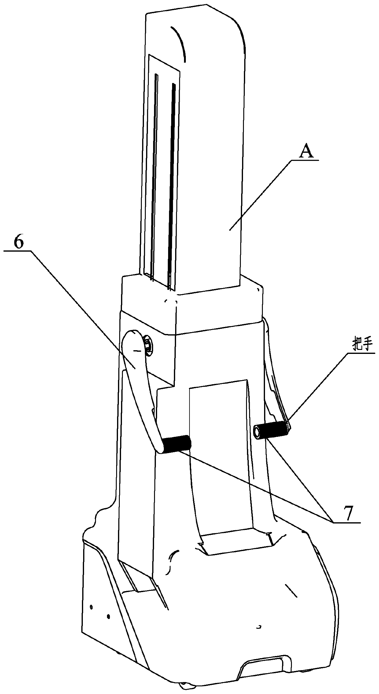
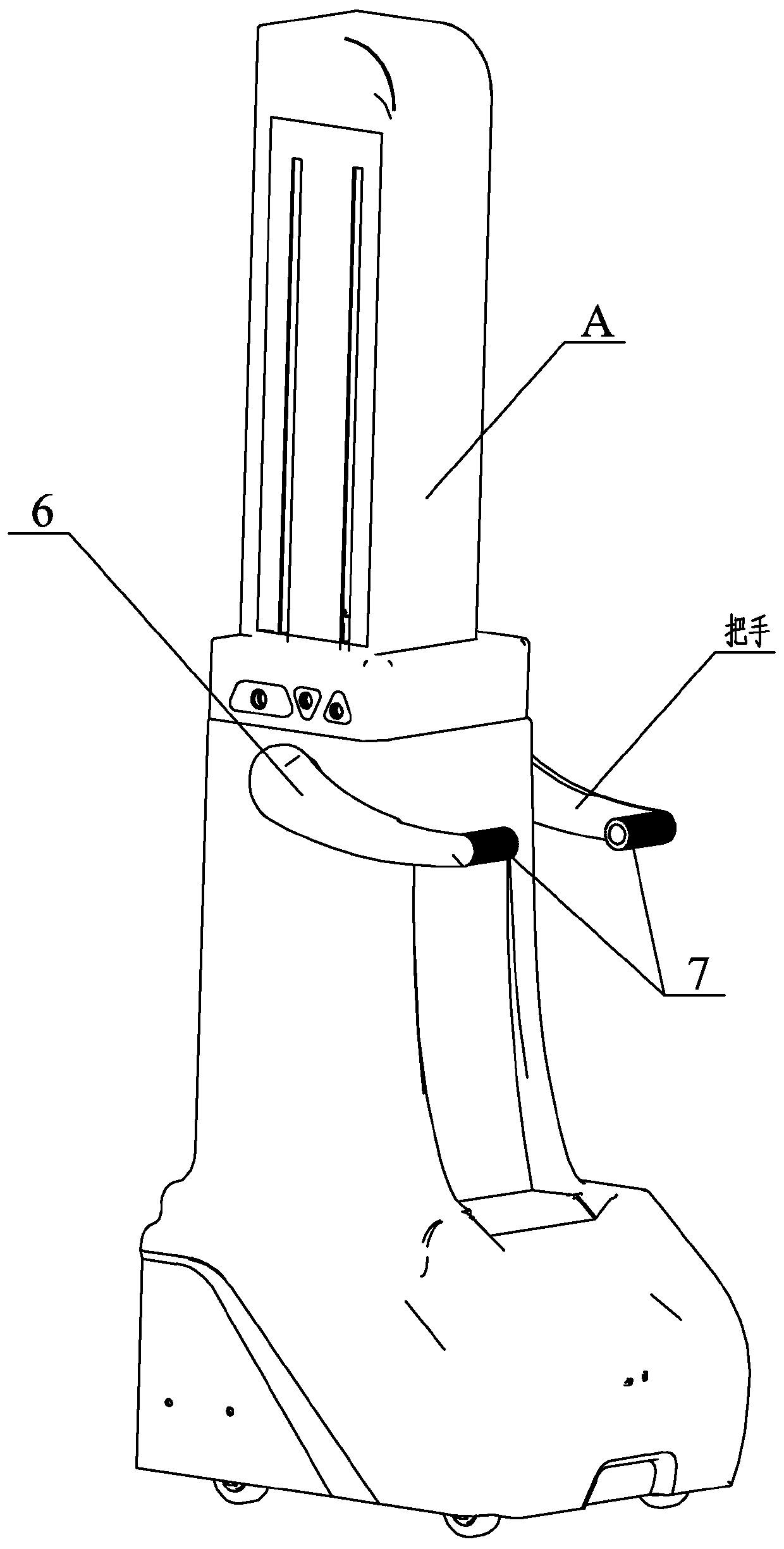
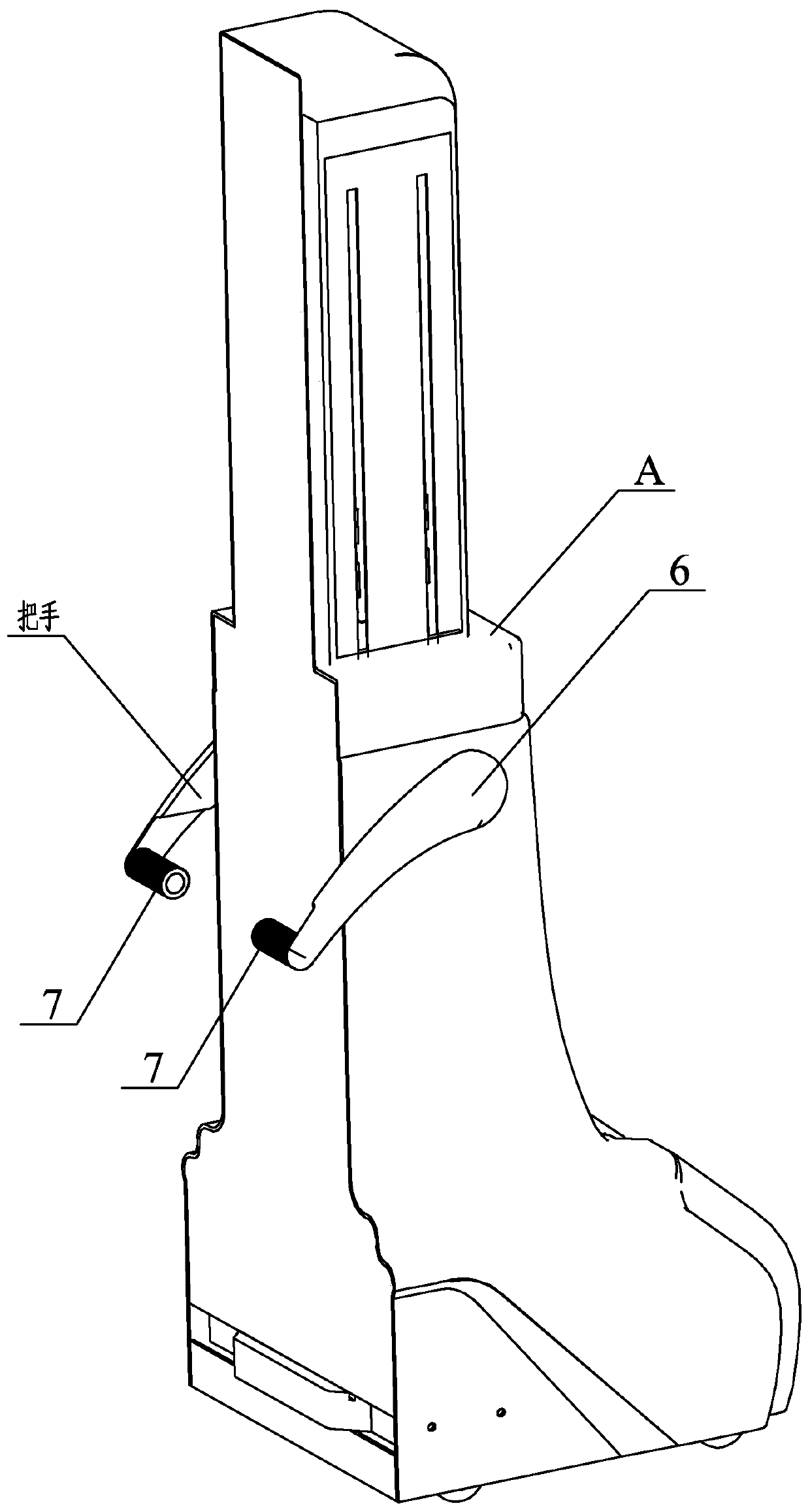
[0027] Specific implementation mode one: combine Figure 1 to Figure 9 Describe this embodiment. A handle for a surgical robot mobile trolley in this embodiment includes a handle fixture 1, a handle shaft 2, a limit assembly, a handle 6, and a handle 7. The handle fixture 1 is embedded and installed on the surgical robot. On the mobile trolley A, the limit assembly is installed on the handle shaft 2. The handle fixing part 1 realizes three states of standby, forward push and backward push by plugging and unplugging at different positions on the handle shaft 2. One end of the handle 6 It is connected with the handle fixing part 1, and the other end of the handle 6 is connected with the handle 7.

specific Embodiment approach 2

[0028] Specific implementation mode two: combination Figure 4 To illustrate this embodiment, the handle fixing part 1 of this embodiment includes a disc base 1-1 and a position adjustment sleeve 1-2, and the position adjustment sleeve 1-2 is arranged on the disc base 1-1 and integrated; Wherein, the inner side wall of the position adjustment sleeve 1-2 is provided with a boss 1-3 near the side of the disc base 1-1, and the inner side wall of the position adjustment sleeve 1-2 is provided with a protrusion 1-4. A circular groove 1-5 is provided on the inner side wall of the adjustment sleeve 1-2. With such arrangement, the disc base 1-1 is connected with the inside of the mobile trolley A, which can effectively save the space occupied by the handle. In addition, the position adjustment sleeve 1-2 is convenient for plugging and matching with the structure of the handle shaft 2 . Other compositions and connections are the same as in the first embodiment.

[0029] The handle f...

specific Embodiment approach 3

[0030] Specific implementation mode three: combination Figure 5 to Figure 7 To illustrate this embodiment, the handle shaft 2 of this embodiment includes an insertion shaft 2-1, a connection plate 2-2, a limit post 2-3 and a positioning protrusion 2-4, and the limit post 2-3 is vertically arranged on On the connection plate 2-2, the insertion shaft 2-1 is vertically arranged on the limit post 2-3, and the axes of the insertion shaft 2-1 and the limit post 2-3 are the same, and the positioning protrusion 2-4 is installed In the middle of the end face on the other side of the connection plate 2-2. With such arrangement, the structure on the limiting post 2-3 can be effectively connected with the limiting component, and can cooperate with the handle fixing part 1 when plugging and unplugging. Other compositions and connections are the same as those in Embodiment 1 or Embodiment 2.

[0031] Three through holes 2-5 are provided on the connecting plate 2-2 of the handle shaft 2 i...


PUM


Abstract

The invention discloses a handle for a moving trolley of a surgical robot, and relates to the field of handles. The invention aims to solve the problems that handles of a moving trolley of an existingoperation robot are very inconvenient when reverse pushing is carried out, and when the moving trolley moves to an appointed position, handle assemblies are not adjustable and occupy the working space, so that inconvenience is brought to the work of operation-related workers. A handle fixed part (1) is embedded and mounted on the moving trolley (A) of the surgical robot, a limiting assembly is mounted on a handle shaft (2), the handle fixed part (1) achieves three states of standby state, forward stretching pushing and backward stretching pushing through inserting and pulling at different positions on the handle shaft (2), one end of each of handles (6) is connected with the handle fixed part (1), and the other ends of the handles (6) are connected with handles (7). The handle is used onthe moving trolleys of surgical robots.

Description

technical field [0001] The invention relates to a handle, in particular to a handle used for a mobile trolley of an operation robot. Background technique [0002] Robotic surgery system is a complex integrating multiple modern high-tech means, which has a wide range of uses and has a large number of applications in clinical surgery. Surgeons can operate machines away from the operating table, which is completely different from the traditional concept of surgery. It is a well-deserved revolutionary surgical tool in the field of minimally invasive surgery in the world. Some tertiary hospitals in my country have also begun to use surgical robots to complete surgical operations. [0003] With the development and use of surgical robots, factors in details other than technical issues are constantly being discovered. For example, when the handgrip pushes the mobile trolley to move, the position of the handle assembly is fixed, which is very inconvenient for reverse pushing. When...

Claims


Application Information

Patent Timeline
Patent Type & Authority Applications(China)
IPC IPC(8): A61B50/13
CPCA61B50/13
Inventor 付宜利潘博宋涛
Owner 杭州唯精医疗机器人有限公司
Why Eureka
Try Eureka