A turbulence generating device suitable for rapid sorting of fine particles
A generating device and fine particle technology, applied in flotation, solid separation, etc., can solve the problems of increasing operating costs and increasing energy consumption, and achieve the effects of low cost, increased turbulence intensity, and simple structure
- Summary
- Abstract
- Description
- Claims
- Application Information
AI Technical Summary
Problems solved by technology
Method used
Image
Examples
Embodiment 1
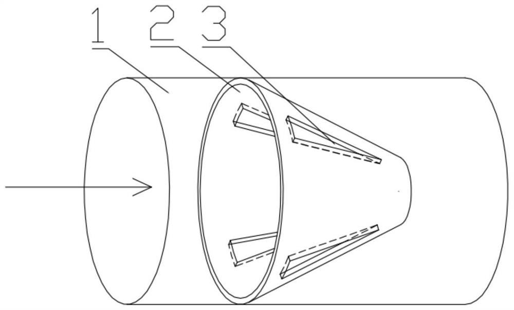
[0021] A turbulent flow generating device suitable for rapid separation of fine particles, comprising a cylindrical pipe flow section 1, and several conical rings 2 arranged in the pipe flow section, wherein each conical ring 2 is arranged along the pipe flow section The axial direction of the conical rings 2 is evenly arranged, and the interval between the conical rings 2 is 15mm. The installation direction of the conical rings 2 in the pipe flow section 1 is set so that the slurry flows from the bottom surface to the top surface; the outer diameter of the bottom surface of the conical rings D. 1 The same as the inner diameter of pipe flow section 1, the outer diameter D of the top surface of the conical ring 2 and the outer diameter of the bottom surface D 1 The ratio is 0.4, and the angle between the outer wall of the conical ring and the inner wall of the pipe flow section is 25°. In order to avoid energy loss, there is no gap between the edge of the bottom surface of the...
Embodiment 2
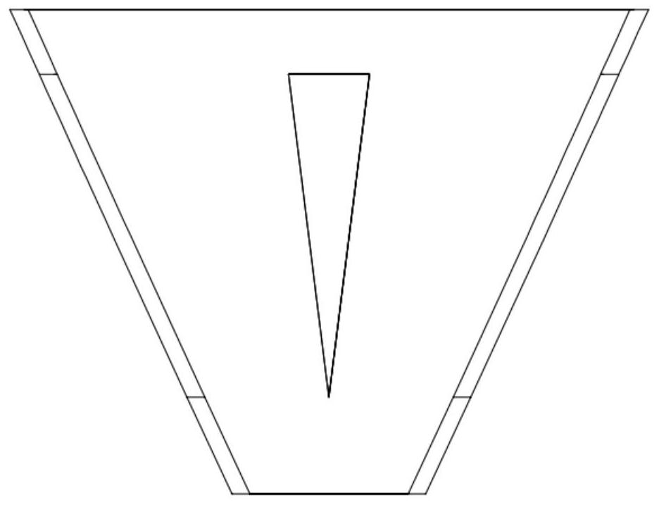
[0023] Such as Figure 1 to Figure 3 As shown, a turbulence generating device suitable for rapid separation of fine particles includes a cylindrical pipe flow section 1, and also includes several conical rings 2 arranged in the pipe flow section, wherein each conical ring 2 is along the The axial direction of the pipe flow section is evenly arranged, and the interval between the conical rings 2 is 20mm. The installation direction of the conical rings 2 in the pipe flow section 1 is set so that the slurry flows from the bottom surface to the top surface; the bottom surface of the conical rings The outer diameter D 1 The same as the inner diameter of pipe flow section 1, the outer diameter D of the top surface of the conical ring 2 and the outer diameter of the bottom surface D 1 The ratio is 0.6, and the angle between the outer wall of the conical ring and the inner wall of the pipe flow section is 30°. In order to avoid energy loss, there is no gap between the edge of the bo...
Embodiment 3
[0025] A turbulent flow generating device suitable for rapid separation of fine particles, comprising a cylindrical pipe flow section 1, and several conical rings 2 arranged in the pipe flow section, wherein each conical ring 2 is arranged along the pipe flow section The axial direction of the conical rings 2 is evenly arranged, and the interval between the conical rings 2 is 25mm. The installation direction of the conical rings 2 in the pipe flow section 1 is set so that the slurry flows from the bottom surface to the top surface; the outer diameter of the bottom surface of the conical rings D. 1 The same as the inner diameter of pipe flow section 1, the outer diameter D of the top surface of the conical ring 2 and the outer diameter of the bottom surface D 1 The ratio is 0.6, and the angle between the outer wall of the conical ring and the inner wall of the pipe flow section is 45°. In order to avoid energy loss, there is no gap between the edge of the bottom surface of the...
PUM
 Abstract
Description
Claims
Application Information
 - R&D
- Intellectual Property
- Life Sciences
- Materials
- Tech Scout
- Unparalleled Data Quality
- Higher Quality Content
- 60% Fewer Hallucinations
Browse by: Latest US Patents, China's latest patents, Technical Efficacy Thesaurus, Application Domain, Technology Topic, Popular Technical Reports.
© 2025 PatSnap. All rights reserved.Legal|Privacy policy|Modern Slavery Act Transparency Statement|Sitemap|About US| Contact US: help@patsnap.com


