Multi-section stirring and circulating slurry mixing equipment and method

A slurry mixing and equipment technology, applied in chemical instruments and methods, mixers, flotation, etc., can solve the problems of high dispersion, high strengthening, and efficient collision contact of fine ore particles, which can improve energy utilization, strengthen The effect of mixing pulp and avoiding the effect of flotation entrainment

Pending Publication Date: 2021-12-28
CHINA UNIV OF MINING & TECH
View PDF11 Cites 2 Cited by
  • Summary
  • Abstract
  • Description
  • Claims
  • Application Information

AI Technical Summary

Problems solved by technology

[0005] In view of the above analysis, the embodiment of the present invention aims to provide a multi-stage stirring circulation slurry mixing equipment and method to solve the problem that the exist

Method used


Image

  • Multi-section stirring and circulating slurry mixing equipment and method
  • Multi-section stirring and circulating slurry mixing equipment and method
  • Multi-section stirring and circulating slurry mixing equipment and method

Examples


Embodiment 1

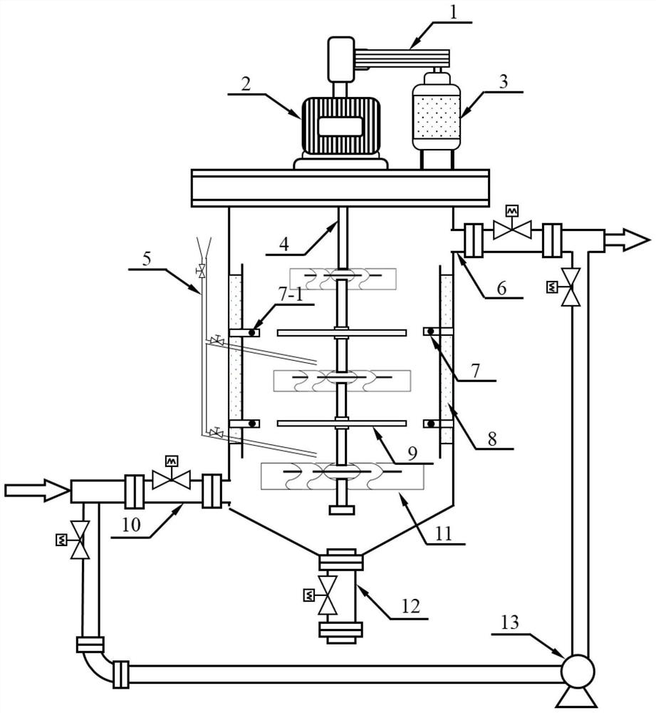
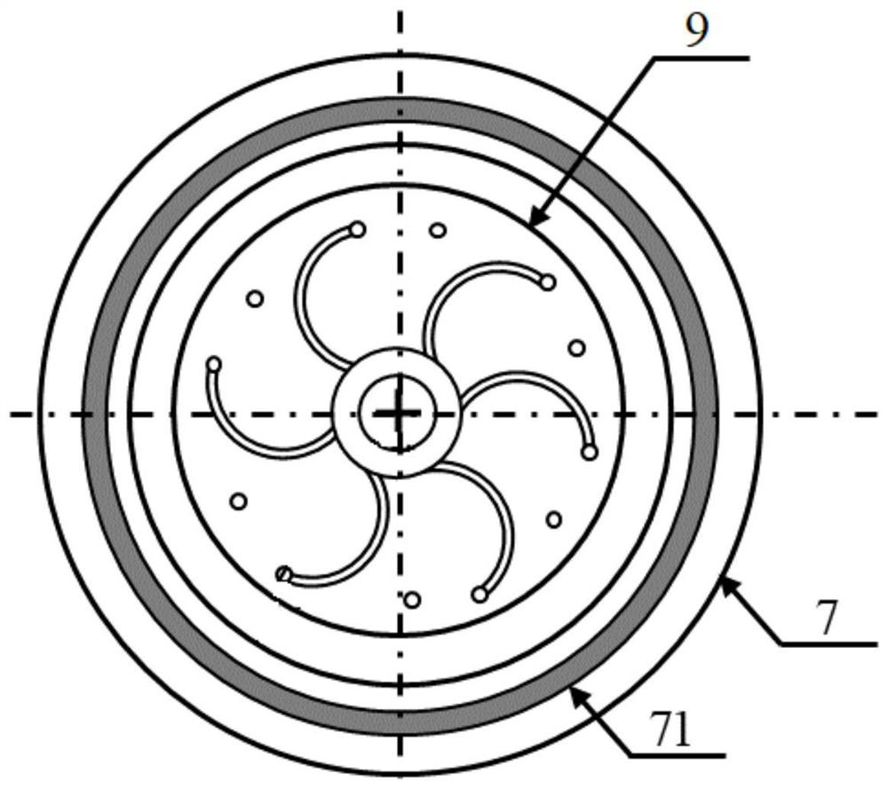
[0044] A specific embodiment of the present invention, such as figure 1 As shown, a multi-stage stirring cycle pulping equipment is disclosed, including a pulping bucket, a diversion disc paddle 9 and a stirring impeller 11 are arranged in the pulping bucket, and the diversion disc paddle 9 moves the inside of the pulping bucket from top to bottom. The lower section is divided into multiple sections of forced stirring and pulping areas, and the stirring impellers 11 are arranged in the forced stirring and pulping areas, and the radius of the stirring impellers 11 in each forced stirring and pulping area is set in a gradient manner.

[0045] Compared with the prior art, the multi-stage forced stirring circulation slurry mixing equipment based on energy regulation provided by this embodiment has a stirring impeller with a gradient radius in the mixing slurry tank to control the stepwise input of energy in the mixing process and improve the mixing process. The energy utilization ...

Embodiment 2

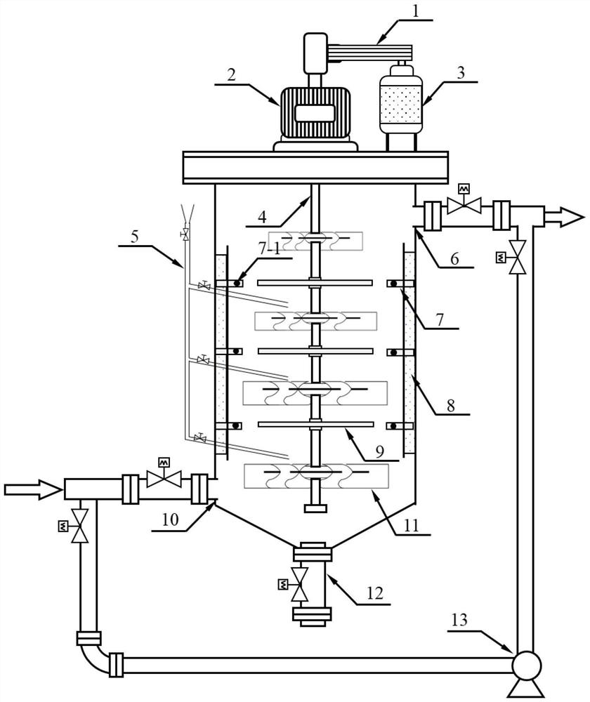
[0063] A specific embodiment of the present invention, such as Figure 5 As shown, a multi-stage stirring cycle pulping equipment is disclosed. The difference from Embodiment 1 is that the height and / or radius of the stirring impeller 11 and the guide disk paddle 9 in the pulping tank increase sequentially from top to bottom, The gap between the annular baffle 7 and the guide disc paddle 9 decreases from top to bottom.

[0064] In this embodiment, the passage time of the pulp decreases from bottom to top with the size of the gap, and the gap between the bottom annular baffle plate 7 and the diversion disc pulp 9 is small, resulting in a high degree of turbulence dissipation, and prolonging the passage time of the pulp at the same time. It is beneficial to improve the effect of forced shear mixing, strengthen the erasure of fine mud on the particle surface and the dispersion of chemicals, especially suitable for materials with a large content of fine mud. Other structures and ...

Embodiment 3

[0066] A specific embodiment of the present invention, such as Image 6 As shown, a multi-stage stirring cycle pulping equipment is disclosed. The difference from Embodiment 1 is that the height and / or radius of the stirring impeller 11 and the guide disk paddle 9 in the pulping tank increase sequentially from top to bottom, The gap between the annular baffle 7 and the guide disc paddle 9 is consistent from top to bottom, that is, the radius of the inner ring of the annular baffle 7 increases sequentially from top to bottom.

[0067] In this embodiment, the pulping intensity is kept in a gradient setting, and the pulp passing time is kept equal from top to bottom. On the basis of ensuring the pulping effect, the pulping amount per unit time of the equipment is increased, and it is suitable for ordinary mines with less fine mud content. material type. Other structures and beneficial effects are the same as those in Embodiment 1, and will not be repeated here.


PUM


Abstract

The invention relates to multi-section stirring and circulating slurry mixing equipment and method, belongs to the technical field of mineral flotation stirring slurry mixing, and solves the problem that slurry mixing equipment and method in the prior art are difficult to meet the requirements of high dispersion, high strengthening and efficient collision contact required by fine ore grains. The device comprises a slurry mixing barrel, wherein a flow guide disc paddle and stirring impellers are arranged in the slurry mixing barrel, the flow guide disc paddle divides the interior of the slurry mixing barrel into multiple sections of forced stirring slurry mixing areas from top to bottom, the stirring impellers are arranged in the forced stirring slurry mixing areas, and the radiuses of the stirring impellers in the forced stirring slurry mixing areas are arranged in a gradient mode. According to the invention, multi-section stirring circulation slurry mixing is adopted, the radius of the stirring impeller is arranged in a gradient manner, gradient input of energy is realized, and the slurry mixing effect is good.

Description

technical field [0001] The invention relates to the technical field of mineral flotation stirring and pulping, in particular to a multi-stage stirring cycle pulping equipment and method. Background technique [0002] Flotation is the most economical and effective separation method for coal and mineral resources, especially for the large-scale recovery of valuable components in fine-grained and micro-fine-grained low-quality coal and strategic mineral resources. The flotation process is carried out according to the surface and interface properties of the particles. The particles with good surface hydrophobicity are easy to attach to the air bubbles and float up as concentrates, while the hydrophilic gangue particles are left in the pulp and discharged as tailings. With the widespread application of mechanized mining and dense media beneficiation technology, problems such as large amount of floating coal slime, large content of fine particles and intergrowth, and narrow effect...

Claims


Application Information

Patent Timeline
IPC IPC(8): B03D1/14B03D1/16B01F11/02B03D103/08
CPCB03D1/14B03D1/1443B03D1/145B03D1/1456B03D1/1475B03D1/16B03D2203/08
Inventor 桂夏辉邢耀文丁世豪曹亦俊谢明辉李永改王磊
Owner CHINA UNIV OF MINING & TECH
Why Eureka
Try Eureka