Copper bar machining equipment

A technology for processing equipment and processing mechanisms, applied in metal processing equipment, manufacturing tools, feeding devices, etc., can solve the problems of increased procurement and manufacturing costs, low work efficiency, waste of time, etc., to improve production efficiency and save labor costs. Effect

Inactive Publication Date: 2020-02-11
苏州凯艾帝电气有限公司
View PDF0 Cites 3 Cited by
  • Summary
  • Abstract
  • Description
  • Claims
  • Application Information

AI Technical Summary

Problems solved by technology

Usually, when copper bars are made into equipment parts, they need to be broken, punched or bent. At present, each process is processed by special equipment. These equipment are generally driven by hydraulic power. Therefore, , each piece of equipment is equipped with a hydraulic system, which increases procurement and manufacturing costs
In addition, since each device can only complete one process, when the process is completed, the copper bar needs to be transferred to the next device for further processing. The copper bar is transferred many times, which wastes time and reduces work efficiency.

Method used


Image

  • Copper bar machining equipment
  • Copper bar machining equipment
  • Copper bar machining equipment

Examples


Embodiment Construction

[0026] The specific embodiments of the present invention will be further described below in conjunction with the accompanying drawings. It should be noted here that the descriptions of these embodiments are used to help understand the present invention, but are not intended to limit the present invention. In addition, the technical features involved in the various embodiments of the present invention described below may be combined with each other as long as they do not constitute a conflict with each other.

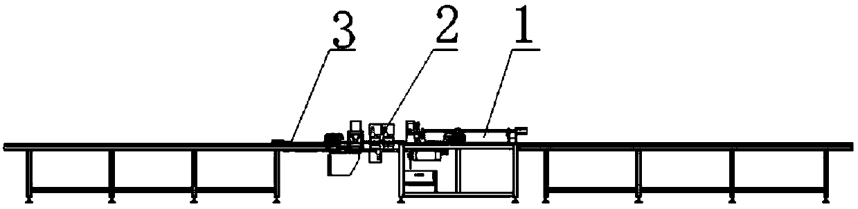
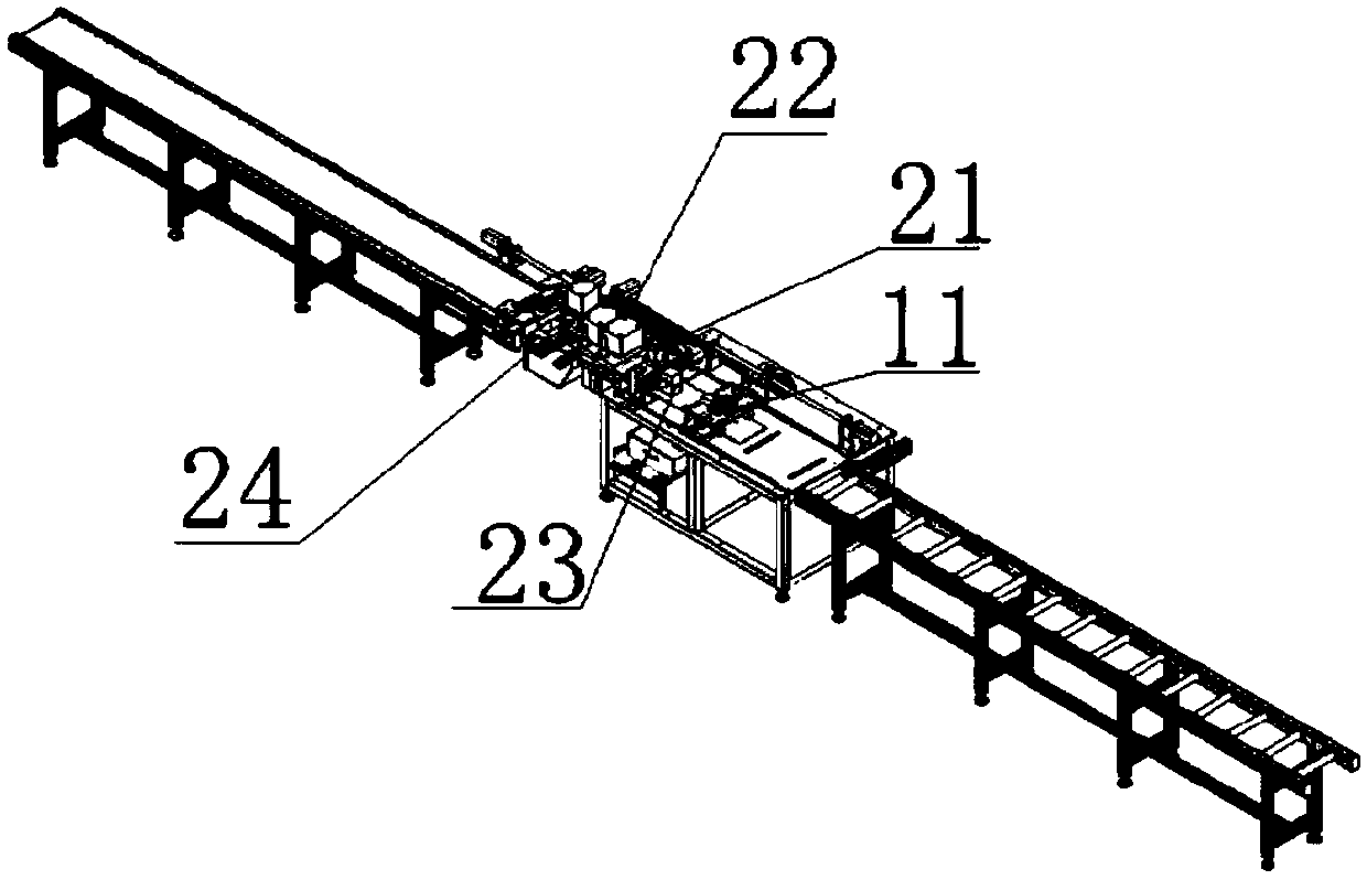
[0027] refer to figure 1 , figure 2 , image 3 As shown, a copper bar processing equipment includes a feeding mechanism 1, a processing mechanism 2, a discharging mechanism 3 and a control device connected in sequence, and the control device is connected to the feeding device 1, the processing device 2, the discharging device, respectively. The device 3 is connected; the feeding mechanism 1 includes a transmission device, a first positioning device, and a second posi...


PUM


Abstract

The invention discloses copper bar machining equipment. The copper bar machining equipment comprises a feeding mechanism, a machining mechanism, a discharging mechanism and a control device, wherein the feeding mechanism, the machining mechanism, the discharging mechanism and the control device are sequentially connected, the control device is connected with the feeding device, the machining device and the discharging device, the feeding mechanism comprises a transmission device, a first positioning device, a second positioning device which are connected with the control device, the transmission device comprises a screw rod, a motor and a roller cylinder, the motor and the roller cylinder are connected with the control device, the motor is connected with the screw rod, the screw rod is arranged at the two ends of the roller barrel in a manner of being perpendicular to the roller barrel, the first positioning module is connected with the screw rod through feed screw nuts, and the secondpositioning device is arranged on the roller barrel in a manner of being perpendicular to the first positioning device. According to the scheme, the structure design is reasonable, the multi-purposemachine can be realized, the full process automation of copper bar production is realized, the production efficiency of copper bar machining is improved, and the labor cost is saved.

Description

technical field [0001] The invention relates to the technical field of copper bar processing, in particular to an automatic copper bar processing equipment. Background technique [0002] Copper bars are also called copper bus bars or copper bus bars. Copper bars are widely used in electrical equipment, especially complete power distribution devices. Usually, when copper bars are made into equipment parts, they need to be broken, punched or bent. At present, each process is processed by special equipment. These equipment are generally driven by hydraulic power. Therefore, , each piece of equipment is equipped with a set of hydraulic systems, which increases procurement and manufacturing costs. In addition, since each device can only complete one process, when the process is completed, the copper bar needs to be transferred to the next device for further processing. The copper bar is transferred many times, which wastes time and reduces work efficiency. Contents of the inve...

Claims


Application Information

Patent Timeline
Patent Type & Authority Applications(China)
IPC IPC(8): B21D43/02B21D43/00B21D35/00
CPCB21D35/002B21D43/003B21D43/021B21D43/027
Inventor 包云
Owner 苏州凯艾帝电气有限公司
Why Eureka
Try Eureka