
Correcting device and assembling and correcting method of printer roller

A calibration device, printer technology, applied in the direction of metal processing, metal processing equipment, manufacturing tools, etc., to achieve the effect of improving the stability of handling, improving the quality of press-fit assembly, and improving the efficiency of handling

Active Publication Date: 2020-02-11
威海莱林精密机械有限公司
View PDF9 Cites 2 Cited by
  • Summary
  • Abstract
  • Description
  • Claims
  • Application Information

AI Technical Summary

Problems solved by technology

[0004] The purpose of the present invention is to solve the above-mentioned problems of the existing printer roller shaft assembly production equipment, and to provide a printer roller shaft calibration device that realizes automatic calibration of the roller shaft and improves the efficiency and quality of the calibration of the roller shaft

Method used


Image

  • Correcting device and assembling and correcting method of printer roller
  • Correcting device and assembling and correcting method of printer roller
  • Correcting device and assembling and correcting method of printer roller

Examples


Embodiment Construction

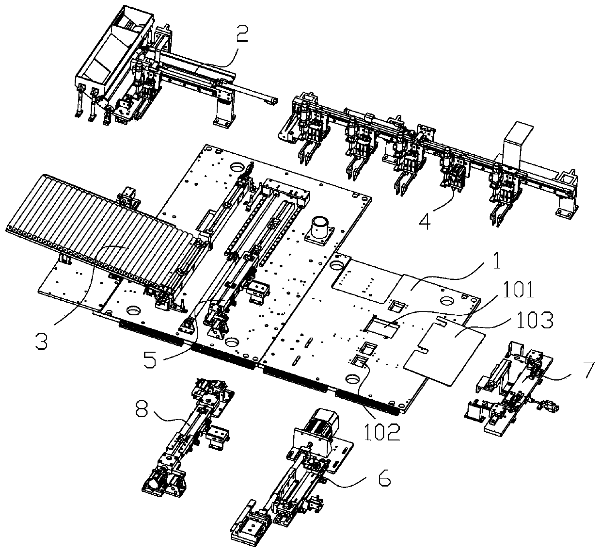
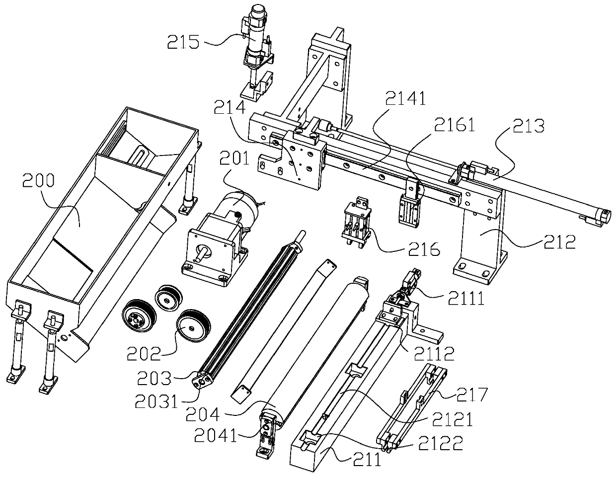
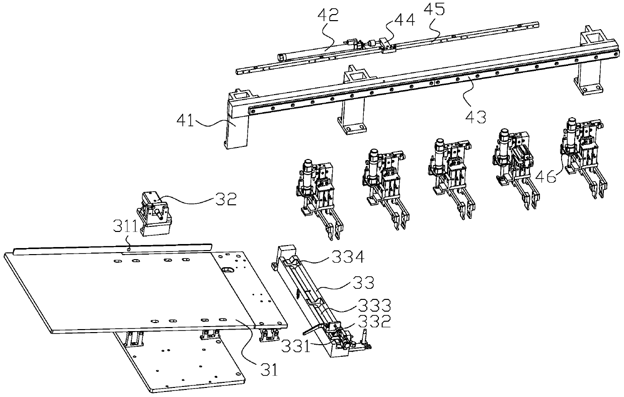
[0025] like figure 1 As shown, a printer roller assembly production equipment includes a frame 1, a shaft feeding and handling device 2, a sponge feeding device 3, a sponge cutting device 6, a shaft end removing device 7, an assembly correction system and a control system; The assembly correction system consists of a sponge transport device 4 , an assembly device 5 and a correction device 8 . The shaft feeding and handling device 2 is arranged at the rear of the frame 1, and the shaft feeding and handling device 2 is used to feed and transport the shaft to the assembly device 5; the sponge feeding device 3, the sponge handling device 4, the assembly device 5, The correction device 8, the sponge cutting device 6 and the shaft end removal device 7 are respectively arranged on the front part of the frame 1, the sponge feeding device 3 is used to feed the shaft, and the sponge handling device 4 is used to transport the sponge to the On the sponge assembly device 5, the sponge cut...


PUM


Abstract

The invention relates to the technical field of printers, and discloses a correcting device of a printer roller. The correcting device comprises a moving mechanism, a rotating mechanism and a clampingand correcting mechanism, wherein the moving mechanism is used for clamping and limiting the roller back and forth, the rotating mechanism is used for driving the roller to rotate, and the clamping and correcting mechanism is used for clamping and correcting the roller. The correcting device has the advantages that the correcting effect and the clamping effect of the printer roller are further improved, and the product quality and the structural strength of the whole roller are improved.

Description

technical field [0001] The invention relates to the technical field of printers, in particular to a printer roller shaft correction device, roller shaft assembly production equipment and a method thereof. Background technique [0002] Printing technology has developed rapidly in recent years. After years of exploration, printing has developed from the original output of characters and simple graphics to the current multi-functional image processing. Due to the increasingly high requirements for industrial automation, automatic printers have great application prospects in industrial product marking and civilian printing of photos, documents and other fields. Therefore, it has high work efficiency, wide application range and good printing quality. Automatic printers can provide convenience for people's lives. [0003] The sponge and rotating shaft of the current printer are assembled by manually inserting the shaft into the sponge, positioning and correcting by other position...

Claims


Application Information

Patent Timeline
IPC IPC(8): B23P19/027B23P19/10B23P19/00
CPCB23P19/001B23P19/027B23P19/10
Inventor 林佳琳徐建伟刘敏
Owner 威海莱林精密机械有限公司
Learn More