
An automatic flanging equipment for reinforced plate production

A reinforcement plate and automatic turning technology, which is applied in the direction of lifting devices, workbenches, manufacturing tools, etc., can solve the problems of manual labor, shaking or stretching, and heavy weight of the reinforcement plate, so as to realize automation, improve work efficiency, and reduce manual work. The effect of the operation

Active Publication Date: 2021-03-02
施剑煌
View PDF11 Cites 0 Cited by
  • Summary
  • Abstract
  • Description
  • Claims
  • Application Information

AI Technical Summary

Problems solved by technology

[0002] Reinforcement plate is a common connecting part in construction machinery. In construction machinery, some parts can only be fixed by welding. During long-term use, the parts will shake or stretch due to the movement of construction machinery. , In this case, the firmness of each component through welding cannot meet the requirements, which will easily lead to the separation of the components, resulting in losses;
[0003] Nowadays, when making reinforcement boards, it is generally necessary to treat the surface of the reinforcement board. Due to the heavy weight of the reinforcement board, after one side is processed, it will be laborious to use manual flanging. Therefore, we propose a reinforcement board Automatic flanging equipment for production, used to solve the problems raised above

Method used


Image

  • An automatic flanging equipment for reinforced plate production
  • An automatic flanging equipment for reinforced plate production
  • An automatic flanging equipment for reinforced plate production

Examples


Embodiment 1

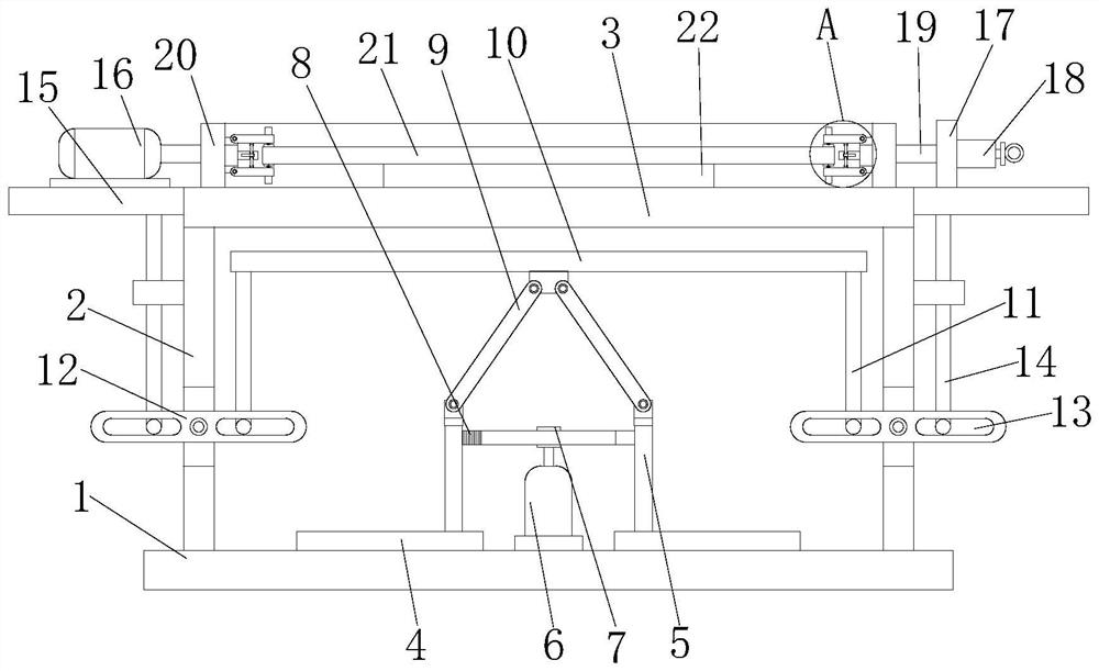
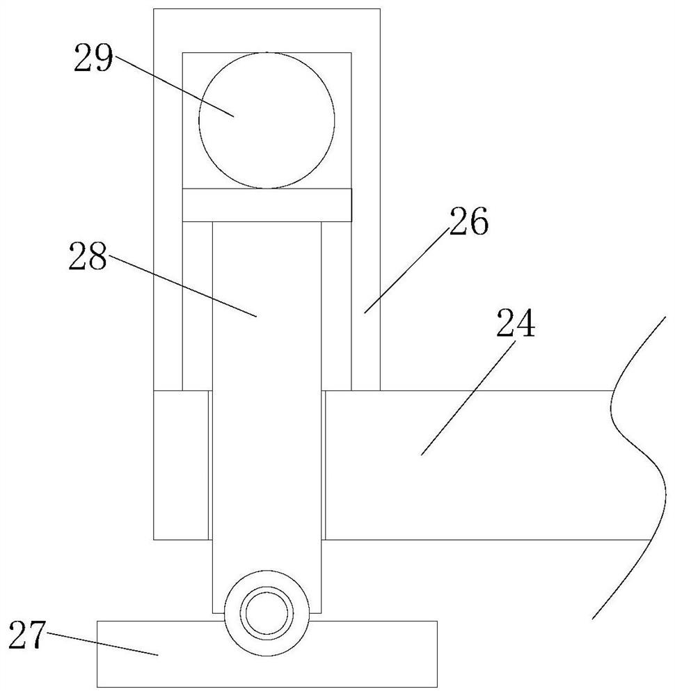
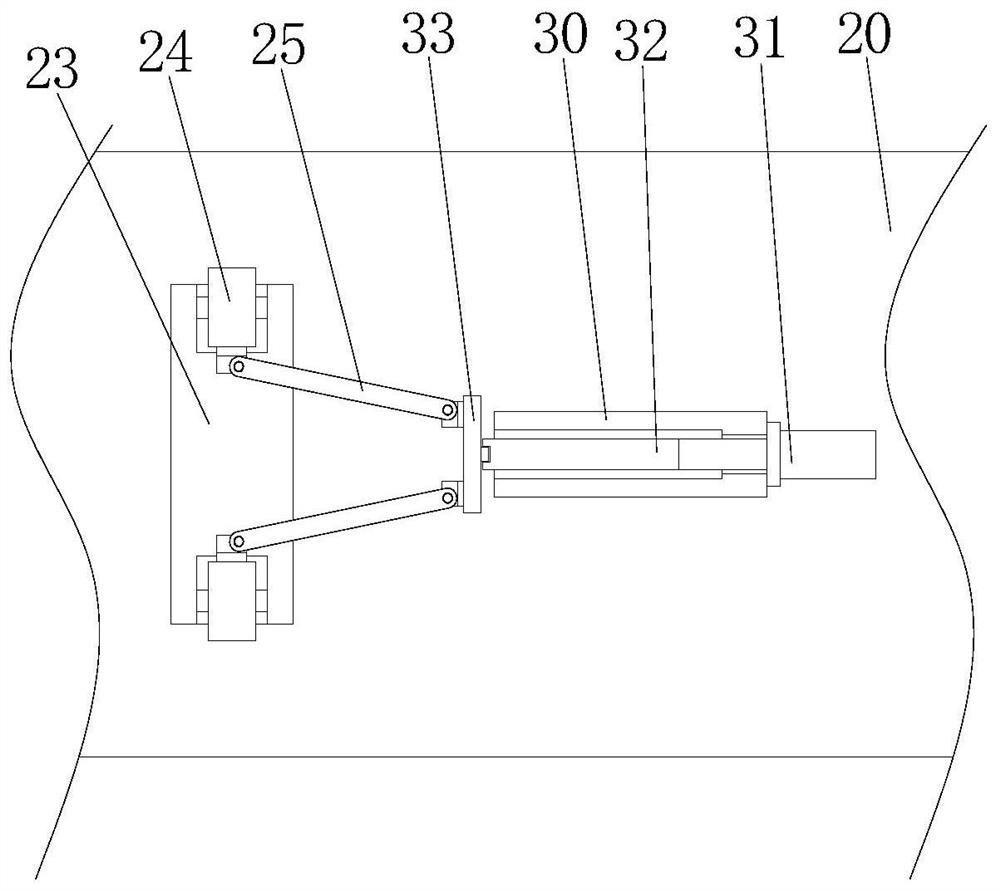
[0028] refer to Figure 1-5 , this embodiment proposes an automatic flanging equipment for the production of reinforced plates, including a base 1, two support columns 2 are symmetrically and fixedly installed on the top of the base 1, and the top of the two support columns 2 is fixedly installed with the same processing Table 3, the top of the base 1 is symmetrically slidably connected with a moving plate 5 between the two supporting columns 2, the top of the base 1 is fixedly installed with a driving motor 6 between the two moving plates 5, and the output shaft of the driving motor 6 A gear 7 is fixedly installed on the top, and a rack 8 is fixedly installed on the side where the two moving plates 5 are close to each other. Rod 9, the tops of the two rotating rods 9 are rotatably connected with the same lifting plate 10, the supporting column 2 is rotatably connected with a linkage rod 12, and one side of the supporting column 2 is slidably connected with a second L-shaped b...

Embodiment 2

[0032] In this embodiment, a mounting hole is opened on the vertical plate 17, and a bearing 39 is fixedly installed in the mounting hole. The connecting column 19 penetrates the bearing 39 and is fixedly connected with the inner ring of the bearing 39. Rotary connection of column 19.

[0033] In this embodiment, the other end of the connecting column 19 is fixedly mounted with a card seat 34, and a push rod 35 is slidably connected to the inner wall of one side of the limit cover 18, and one end of the push rod 35 is movably clamped with the card seat 34, which can be conveniently aligned. The connecting column 19 is limited.

[0034] In this embodiment, a rectangular groove 40 is opened on one side of the card holder 34, and one end of the push rod 35 extends into the rectangular groove 40 and a rectangular plate 37 is fixedly installed thereon. The cooperation between the plate 37 and the rectangular slot 40 can simplify the clamping step.

[0035] In this embodiment, the...


PUM


Abstract

The invention belongs to the field of production and processing of reinforcement boards, in particular to an automatic flanging equipment for the production of reinforcement boards. In view of the heavy weight of the existing reinforcement boards, it would be laborious to use manual flanging after one side is processed. Problem, the following scheme is proposed, which includes a base, two support columns are symmetrically and fixedly installed on the top of the base, and the same processing table is fixedly installed on the top of the two support columns, and the top of the base is symmetrically slidably connected to the two support columns Between the moving plates, the top of the base is fixedly equipped with a driving motor between the two moving plates, the output shaft of the driving motor is fixedly equipped with gears, and the sides of the two moving plates close to each other are fixedly equipped with racks. In the present invention, by sequentially starting the cylinder, the driving motor and the rotating motor, the action of turning over the reinforcing plate can be realized, which can greatly reduce the manual operation of the operator, realize the automation of turning over, and effectively improve the work efficiency.

Description

technical field [0001] The invention relates to the technical field of production and processing of reinforced plates, in particular to an automatic flanging device for the production of reinforced plates. Background technique [0002] Reinforcement plate is a common connecting part in construction machinery. In construction machinery, some parts can only be fixed by welding. During long-term use, the parts will shake or stretch due to the movement of construction machinery. , In this case, the firmness of each component through welding cannot meet the requirements, which will easily lead to the separation of the components, resulting in losses; [0003] Nowadays, when making reinforcement boards, it is generally necessary to treat the surface of the reinforcement board. Due to the heavy weight of the reinforcement board, after one side is processed, it will be laborious to use manual flanging. Therefore, we propose a reinforcement board The automatic flanging equipment for...

Claims


Application Information

Patent Timeline
Patent Type & Authority Patents(China)
IPC IPC(8): B66F19/00B66F13/00B25H1/08
CPCB25H1/08B66F13/00B66F19/00
Inventor 施剑煌江先庆
Owner 施剑煌
Learn More