
A Diode Pumped Laser Module Crystal Bar

A technology for pumping lasers and crystal rods, which is applied in the direction of lasers, semiconductor lasers, laser components, etc., can solve the problems of uneven heat conduction of crystal rods, difficulty in controlling the clamping force of crystal rods, and high average power, so as to reduce the coaxiality Processing accuracy requirements, improving the uniformity of the output spot, and reducing the effect of clamping stress

Active Publication Date: 2018-10-02
INST OF APPLIED ELECTRONICS CHINA ACAD OF ENG PHYSICS
View PDF7 Cites 0 Cited by
  • Summary
  • Abstract
  • Description
  • Claims
  • Application Information

AI Technical Summary

Problems solved by technology

[0004] 1. The heat sink of the upper part of the rod is isolated from the base, and its heat cannot be conducted to the base, resulting in uneven heat conduction between the top and bottom of the crystal rod, resulting in poor uniformity of the output spot of the module
[0005] 2. When working at high frequency, the average power is high, and the heat of the crystal rod is not easy to conduct away, resulting in a sharp decrease in the light output efficiency of the module
[0006] 3. Since the crystal rod is clamped by two sections, a large clamping stress will be generated on the crystal rod, and uneven thermal stress will be added after heating, which intensifies the unevenness of the output spot of the module
[0007] 4. The clamping force of the crystal rod is not easy to control. If the crystal rod is clamped tightly, there will be a large clamping stress on the module crystal rod; otherwise, there will be a risk of axial sliding of the crystal rod after vibration

Method used


Image

  • A Diode Pumped Laser Module Crystal Bar

Examples


Embodiment Construction

[0033] All features disclosed in this specification, or steps in all methods or processes disclosed, may be combined in any manner, except for mutually exclusive features and / or steps.

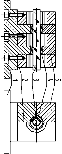
[0034] As shown in the figure, the packaging structure of the crystal rod of the diode-pumped laser module used in the present invention is completely different from the existing packaging structure. First, considering the heat conduction problem of the crystal rod, in order to solve the problem of uniform pressure on the entire surface of the crystal rod, the rod All the heat on the body is transferred out, so the surface around the crystal rod needs to be in contact with the heat-conducting structure. Therefore the present invention has designed a rod heat sink with circular hole, and crystal rod is passed through the circular hole of rod heat sink, so just makes rod heat sink and crystal rod can contact in an all-round way, for the contact section of crystal side, on the crystal rod The hea...


PUM


Abstract

The invention discloses a diode-pumped-laser-module crystal bar. The diode-pumped-laser-module crystal bar comprises a crystal bar body, a base and a cooling mechanism arranged on the bottom face of the base. A plurality of protruding parts connected with the top face of the base are formed in the base in the arranged direction of the crystal bar body, module rings are arranged on the two sides of the protruding parts in the arranged direction of the crystal bar body respectively, bar heat sinks are arranged on all the protruding parts, the crystal bar body penetrates through all the module rings and all the bar heat sinks, the bar heat sinks and the crystal bar body are fixedly connected to be a whole, and pressing blocks are arranged on all the bar heat sinks, and press the bar heat sinks to the protruding parts; as the crystal bar body and the bar heat sinks are directly welded to be a whole, a welding material is fully in contact with the crystal bar body, heat is better guided to the bar heat sinks, the heat stress, caused by uneven heated, of the crystal bar body is reduced, and the evenness of output facula is improved.

Description

technical field [0001] The invention belongs to the technical field of semiconductor lasers, and is specifically aimed at an all-solid-state cooling diode-pumped laser module (referred to as a module), and relates to a method for packaging crystal rods of the module. Background technique [0002] Diode-pumped laser modules are an essential part of solid-state laser systems. The cooling methods of diode-pumped laser modules mainly include liquid cooling and solid-state cooling. Liquid cooling generally involves immersing crystal rods in some liquid for cooling, while solid-state cooling generally directly contacts the crystal rods through heat sinks, and then takes away the heat on the heat sinks through semiconductor refrigeration sheets. The diode-pumped laser described in the present invention The module uses an all-solid-state cooling method. [0003] According to the traditional method, the crystal rod is in direct contact with the rod heat sink, and the rod heat sink ...

Claims


Application Information

Patent Timeline
Patent Type & Authority Patents(China)
IPC IPC(8): H01S3/02H01S3/04H01S3/042H01S5/022H01S5/024
CPCH01S3/025H01S3/0405H01S3/042H01S5/02469H01S5/02365
Inventor 尹新启高松信叶一东雒仲祥魏彬李建民廖原卢飞邹凯王树峰罗佳
Owner INST OF APPLIED ELECTRONICS CHINA ACAD OF ENG PHYSICS
Learn More