AI technical title is built by Patsnap AI team. It summarizes the technical point description of the patent document.
A technology of glass cutting and plastic-steel windows, applied in the field of doors and windows, can solve problems such as single function, and achieve the effect of easy removal
Inactive Publication Date: 2020-02-11
刘培华
View PDF0 Cites 2 Cited by
Summary
Abstract
Description
Claims
Application Information
AI Technical Summary
This helps you quickly interpret patents by identifying the three key elements:
Problems solved by technology
Method used
Benefits of technology
Problems solved by technology
[0002] Glass cutting equipment for plastic-steel windows is a commonly used equipment in the field of doors and windows, but the general glass cutting equipment for plastic-steel windows can only cut strips of fixed specifications, and the function is relatively single
Method used
Image
Click on the blue label to locate the original text in one second.
Reading with bidirectional positioning of images and text.
Examples
specific Embodiment approach 1
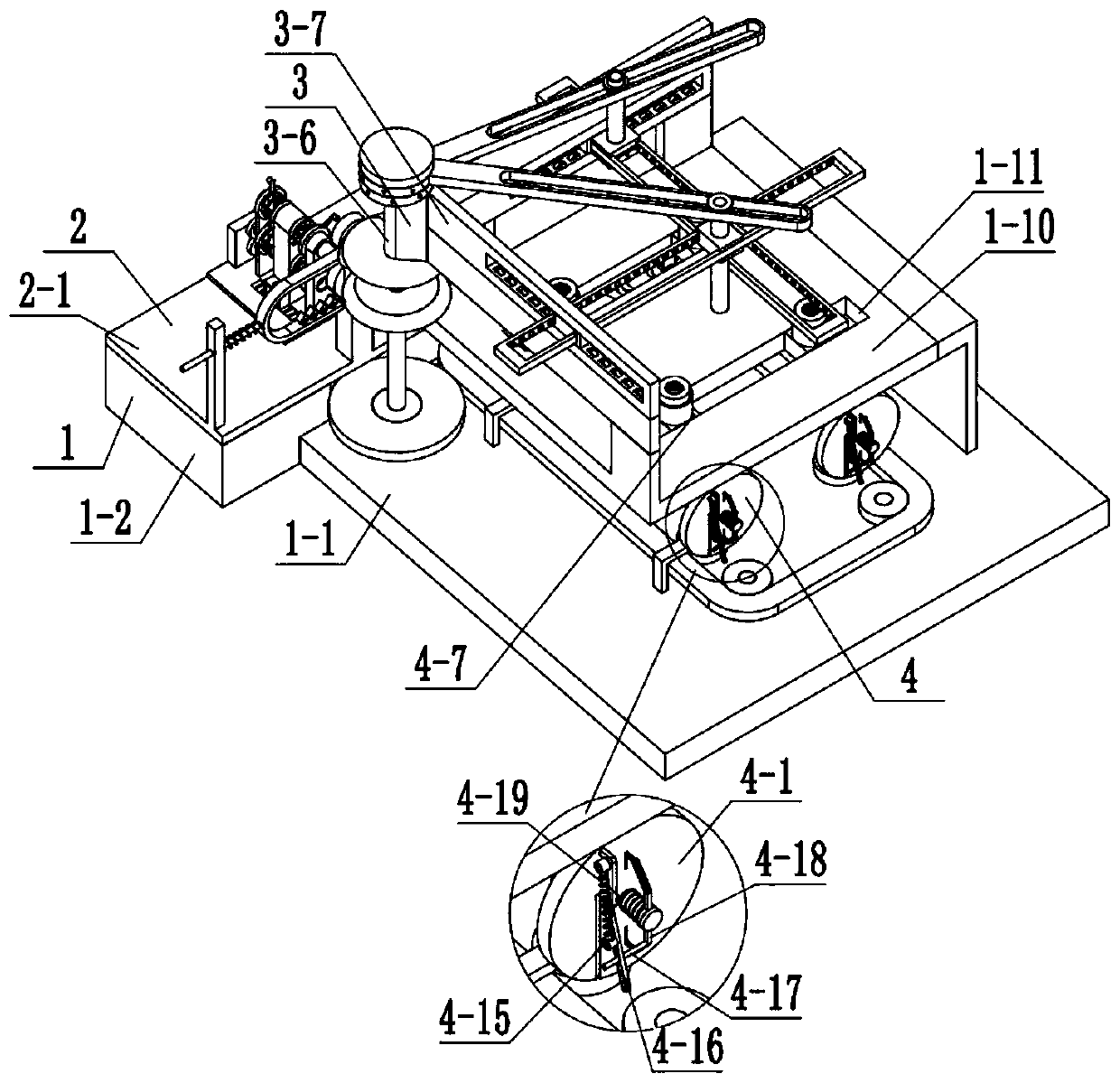
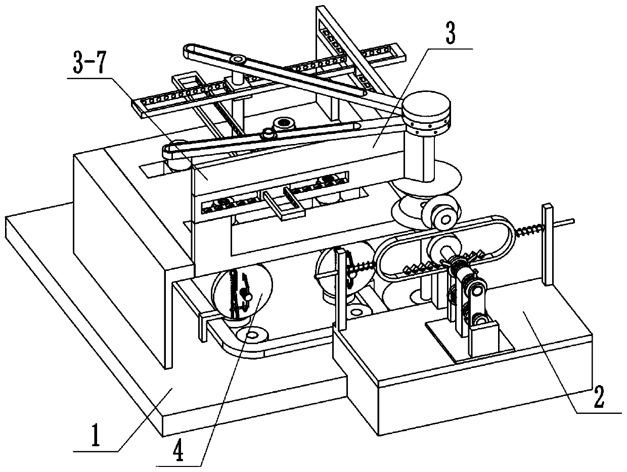
[0044] Combine below Figure 1-25 Describe this embodiment, a glass cutting equipment for plastic-steel windows, including a chassisassembly 1, a power source 2, an XY cutting assembly 3, and an adsorption assembly 4, characterized in that: the power source 2 and the chassis assembly 1, the XY cutting assembly 3 is connected to the power source 2, the adsorption assembly 4 is connected to the chassis assembly 1, and the adsorption assembly 4 is connected to the power source 2.
specific Embodiment approach 2
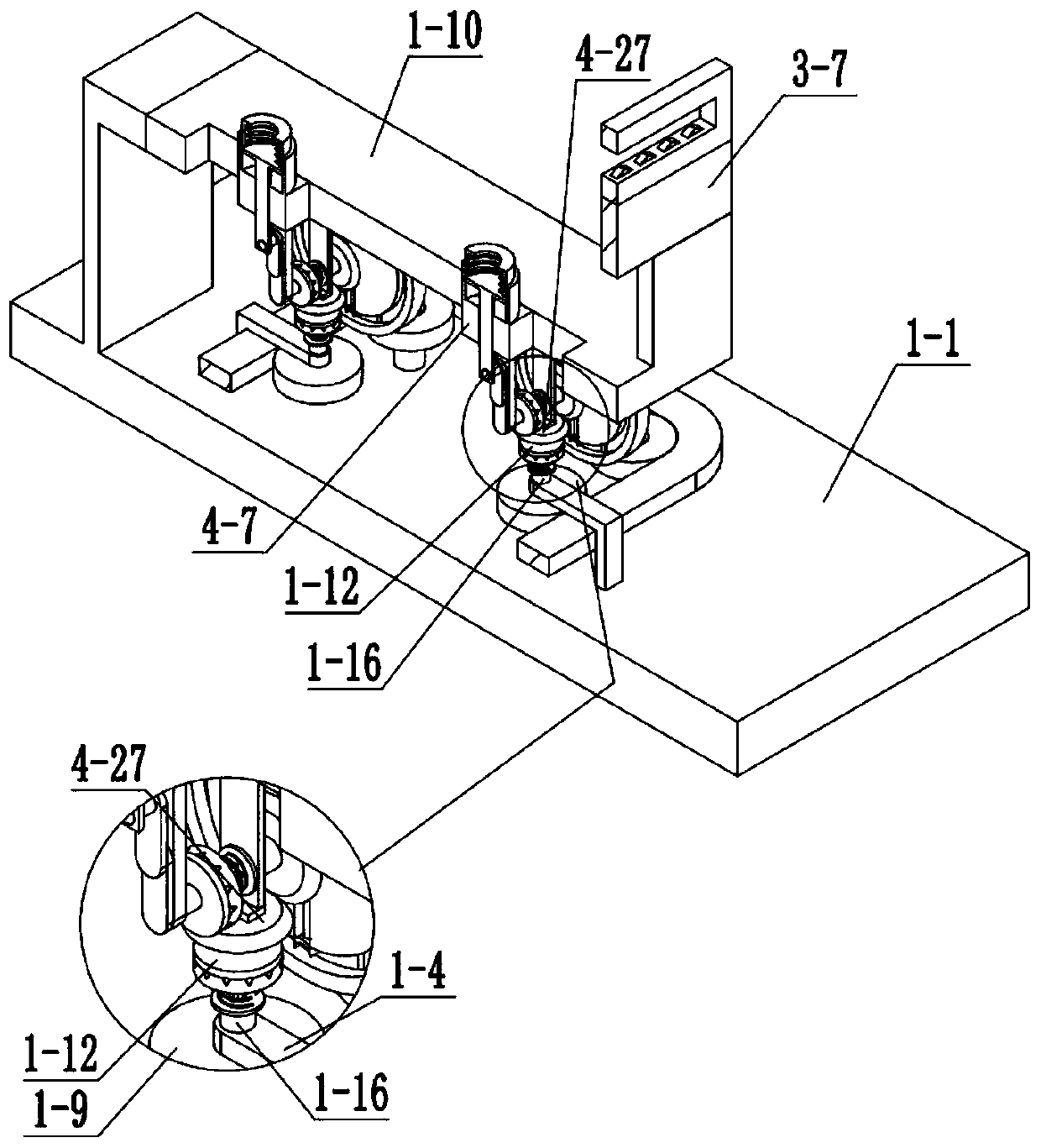
[0046] Combine below Figure 1-25 Describe this embodiment, this embodiment will further explain Embodiment 1, the underframe assembly 1 includes an underframe body 1-1, a fixed boss 1-2, a rotating column 1-3, and a hinged frame 1-4 , Side wall plate 1-5, transmission belt one 1-6, driving pulley one 1-7, driving pulley two 1-8, driving pulley three 1-9, upper end plate 1-10, fixing groove 1-11 , upper clutch lever 1-12, middle clutch lever 1-13, clutch push spring 1-14, connecting cross bar 1-15, connecting sleeve 1-16, clutch groove 1-17, clutch boss 1-18, The fixed boss 1-2 is fixedly connected with the bottom frame body 1-1, the rotating column one 1-3 is fixedly connected with the bottom frame body 1-1, the hinged frame one 1-4 is fixedly connected with the bottom frame body 1-1, and the side wall Plate 1-5 is fixedly connected with chassis body 1-1, driving pulley 1-7 is rotationally connected with chassis body 1-1, driving belt 1-6 is connected with driving pulley 1-7...
specific Embodiment approach 3
[0048] Combine below Figure 1-25Describe this embodiment. This embodiment will further explain Embodiment 1. The power source 2 includes a power base 2-1, a support 2-2, a support 2 2-3, a support 3 2-4, and a support 2-5. , card slot 2-6, mid-end fixed plate 2-7, input motor 2-8, drive spur gear 1 2-9, drive shaft 1 2-10, drive shaft 2 2-11, drive cam 1 2-12, Transmission cam two 2-13, mid-end slide bar 2-14, transmission terminal one 2-15, transmission terminal two 2-16, transmission cam three 2-17, transmission cam four 2-18, lever one 2-19, Fitting slot one 2-20, fitting slot two 2-21, lever two 2-22, positioning outer frame 2-23, horizontal outer frame 2-24, horizontal push spring 2-25, middle end dial 2-26, Meshing straight gear 1 2-27, transmission bevel gear 1 2-28, transmission bevel gear 2 2-29, transmission bevel gear 3 2-30, transmission bevel gear shaft 1 2-31, limit plate 2-32, drive card Rod 2-33, lever push spring A2-34, input straight tooth 1 2-35, middle e...
PUM
Abstract
The invention relates to the field of doors and windows, in particular to glass cutting equipment for plastic steel windows. The equipment can cut glass plates of different lengths and widths, can conveniently fix glass cutters of different specifications, and can improve the glass plate fixing stability. The equipment comprises an underframe combination, a power source, an XY cutting combinationand an adsorption combination. The downward movement amount of an inner end piston along a vertical plate casing pipe is maximum, so that the pressure difference of an external pressure and the pressure in a closed space is maximum, and a glass plate is tightly buckled to a rubber sealing sleeve; when a hinged sliding rod is located at a highest point MAX of a circular sliding groove, the inner end piston returns to an original position, so that the pressure difference between the external pressure and the pressure in the closed space is minimum, and meanwhile the glass plate can be conveniently removed; and when the locating point of the hinged sliding rod in the circular sliding groove has the highest point MAX of the circular sliding groove and a lowest point MIN of the circular slidinggroove, through relative rotation of an upper end clutch rod and a middle end clutch rod, transmission between a driving belt pulley 3 and a hinged rod bevel gear cannot be interfered.
Description
technical field [0001] The invention relates to the field of doors and windows, in particular to a glass cutting device for plastic-steel windows. Background technique [0002] Glass cutting equipment for plastic-steel windows is a commonly used equipment in the field of doors and windows, but general glass cutting equipment for plastic-steel windows can only cut strips of fixed specifications, and has a single function. Contents of the invention [0003] The object of the present invention is to provide a glass cutting device for plastic-steel windows, which can cut glass plates of different lengths and widths; can conveniently fix glass knives of different specifications; and can improve the stability of the fixed glass plates. [0004] The purpose of the present invention is achieved through the following technical solutions: [0005] A glass cutting device for plastic-steel windows, including a chassisassembly, a power source, an XY cutting assembly, and an adsorptio...
Claims
Application Information
Patent Timeline
Application Date:The date an application was filed.
Publication Date:The date a patent or application was officially published.
First Publication Date:The earliest publication date of a patent with the same application number.
Issue Date:Publication date of the patent grant document.
PCT Entry Date:The Entry date of PCT National Phase.
Estimated Expiry Date:The statutory expiry date of a patent right according to the Patent Law, and it is the longest term of protection that the patent right can achieve without the termination of the patent right due to other reasons(Term extension factor has been taken into account ).
Invalid Date:Actual expiry date is based on effective date or publication date of legal transaction data of invalid patent.

