Centrifugal pump for chemical engineering

A centrifugal pump, chemical technology, applied in the direction of pumps, parts of pumping devices for elastic fluids, pump devices, etc., can solve the problems of reduced work efficiency, difficult movement, etc., to achieve convenient maintenance and cleaning, prevent shaking, and convenient The effect of hoisting

Inactive Publication Date: 2020-02-11
ZHENJIANG FUTAIKE FLUID TECH CO LTD
View PDF0 Cites 3 Cited by
  • Summary
  • Abstract
  • Description
  • Claims
  • Application Information

AI Technical Summary

Problems solved by technology

[0002] Chemical centrifugal pumps refer to centrifugal pumps used in the chemical industry. Compared with other types of pumps, chemical centrifugal pumps have the advantages of simple structure, not easy to wear, stable operation, low noise, uniform water outlet, convenient adjustment, and high efficiency. Centrifugal pumps have been widely used. Most of the chemical centrifugal pumps on the market are fixedly connected. However, due to different working conditions, a chemical pump needs to be equipped with a variety of motors. If it cannot be disassembled quickly, it will cause The working efficiency is reduced. During the use of the centrifugal pump, due to the heavy weight of the centrifugal pump, the crane is generally used for hoisting, but it is difficult to move without a crane.

Method used


Image

  • Centrifugal pump for chemical engineering
  • Centrifugal pump for chemical engineering
  • Centrifugal pump for chemical engineering

Examples


Embodiment Construction

[0026] The following will clearly and completely describe the technical solutions in the embodiments of the present invention with reference to the accompanying drawings in the embodiments of the present invention. Obviously, the described embodiments are only some, not all, embodiments of the present invention. Based on the embodiments of the present invention, all other embodiments obtained by persons of ordinary skill in the art without making creative efforts belong to the protection scope of the present invention.

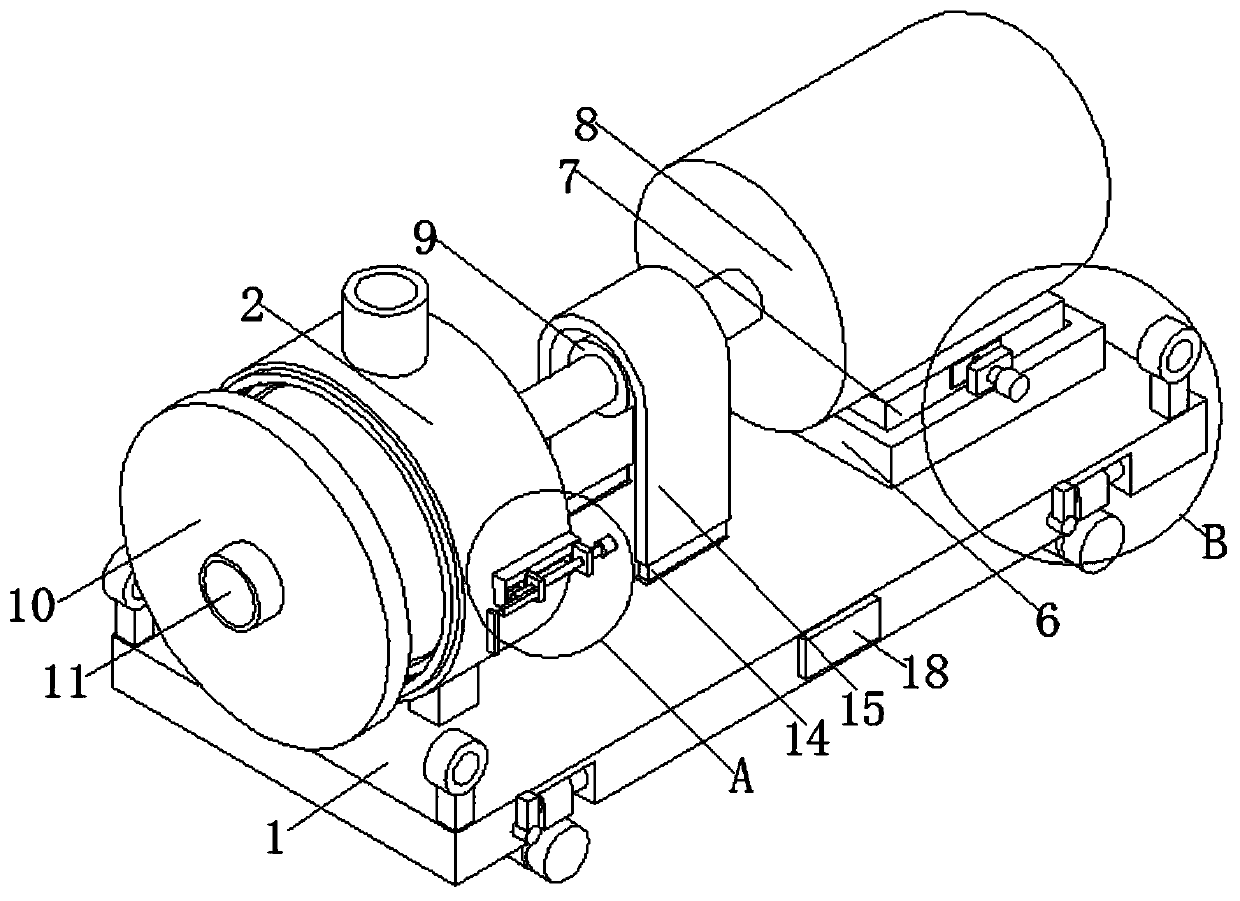
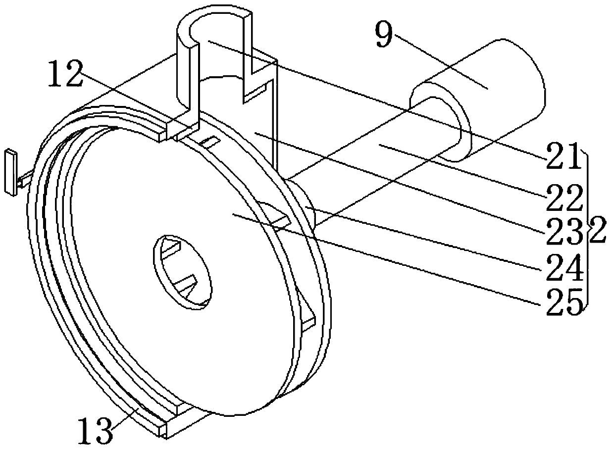
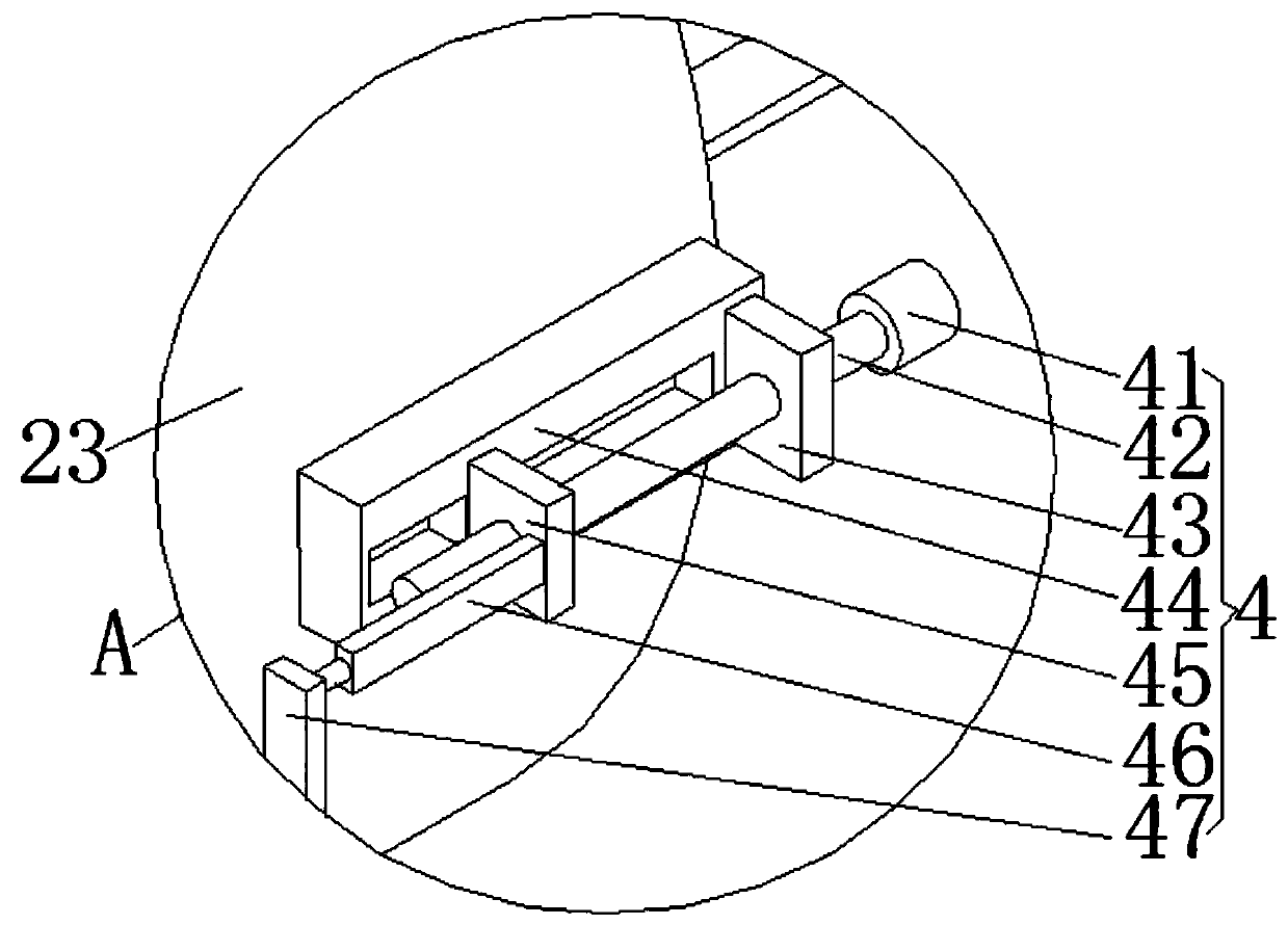
[0027] see Figure 1-4 , the present invention provides a technical solution: a centrifugal pump for chemical industry, including a bottom plate 1, a centrifugal unit 2, a replacement unit 3, a mounting base 6, a base 7, a motor 8 and a coupling 9;

[0028] Bottom plate 1: The right side of the upper surface of the bottom plate 1 is provided with a mounting seat 6, the groove on the top of the mounting seat 6 is matched with the base 7, the top of the base 7 i...


PUM


Abstract

The invention discloses a centrifugal pump for chemical engineering. The centrifugal pump comprises a bottom plate, a centrifugal unit, a replacement unit, a mounting seat, a base, a motor and a coupler; a mounting seat is arranged on the right side of the upper surface of the bottom plate, a groove at the bottom end of the mounting seat is matched with the base, a motor is arranged at the top endof the base, an output shaft of the motor is connected with the right end of the coupler, replacement units are arranged on the left side and the right side of the top end of the mounting seat correspondingly, mounting grooves are formed in the left and right ends of the front and rear sides of the bottom plate, and mobile units are arranged in the mounting grooves; and the centrifugal unit comprises a liquid outlet, a rotating shaft, a pump body, a pipe sleeve and an impeller, the bottom end of the pump body is connected with the left side of the upper surface of the bottom plate through a supporting column, the liquid outlet is formed at the top end of the pump body, the pipe sleeve is arranged in the middle of the right side face of the pump body, and the pipe sleeve is rotationally connected with the rotating shaft. The centrifugal pump for chemical engineering is simple to operate, convenient to move and capable of rapidly disassembling and assembling.

Description

technical field [0001] The invention relates to the technical field of chemical centrifugal pumps, in particular to a chemical centrifugal pump. Background technique [0002] Chemical centrifugal pumps refer to centrifugal pumps used in the chemical industry. Compared with other types of pumps, chemical centrifugal pumps have the advantages of simple structure, not easy to wear, stable operation, low noise, uniform water outlet, convenient adjustment, and high efficiency. Centrifugal pumps have been widely used. Most of the chemical centrifugal pumps on the market are fixedly connected. However, due to different working conditions, a chemical pump needs to be equipped with a variety of motors. If it cannot be disassembled quickly, it will cause The work efficiency is reduced. During the use of the centrifugal pump, due to the heavy weight of the centrifugal pump, it is generally hoisted by a crane, but it is difficult to move without a crane. Contents of the invention [...

Claims


Application Information

Patent Timeline
Patent Type & Authority Applications(China)
IPC IPC(8): F04D13/06F04D29/00F04D29/42F04D15/00F04D29/62F04D29/08F04D29/044F16M3/00
CPCF04D13/06F04D15/00F04D29/007F04D29/044F04D29/086F04D29/426F04D29/628F16M3/00
Inventor 丛小青袁丹青
Owner ZHENJIANG FUTAIKE FLUID TECH CO LTD
Why Eureka
Try Eureka