A roller drying structure and a dryer made of the structure

A dryer and roller technology, applied in dryers, drying, drying goods handling and other directions, can solve the problems of long time required for drying, inconvenient evaporation of internal water, affecting drying efficiency, etc. The effect of improving efficiency, reducing drag, and improving practicality

Active Publication Date: 2021-10-29
SHANXI HEPO POWER GENERATION CO LTD
View PDF0 Cites 0 Cited by
  • Summary
  • Abstract
  • Description
  • Claims
  • Application Information

AI Technical Summary

Problems solved by technology

[0002] A dryer is a device for drying materials. The existing drying equipment generally puts materials into a drying container, and then heats the container to evaporate the moisture in the material to be dried through high temperature. However, in this drying method, the objects to be dried in the container are piled up in blocks, especially some fine particles of mud (such as coal slime, etc.). After forming a dense block structure, the outside of the object to be dried is easy to dry, but for the inside of the object to be dried, because it cannot quickly contact with the external high temperature environment, it is not convenient for the evaporation of internal moisture. It takes a long time to dry, which greatly affects the drying efficiency and also causes a waste of energy. Therefore, it is necessary to design a high-efficiency drying device for this type of to-be-dried objects to achieve its rapid drying. dry, save energy

Method used


Image

  • A roller drying structure and a dryer made of the structure
  • A roller drying structure and a dryer made of the structure

Examples


Embodiment Construction

[0028] The present invention will be further described below with reference to the accompanying drawings and embodiments, and the mode of the present invention includes but not limited to the following embodiments.

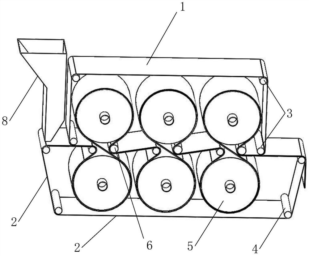
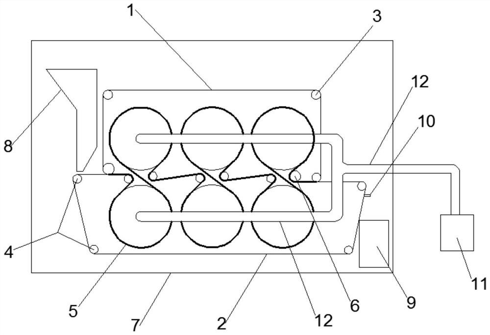
[0029] Such as Figure 1~2 Shown:

[0030] A roller drying structure, by pressing the material to be dried into a flat structure, increasing the area in contact with the ambient temperature and improving the drying efficiency, the specific structure includes a first conveyor belt 1 and a second conveyor belt 2. The combination of two conveyor belts clamps the materials to be dried; the first conveyor belt 1 is limited by the first limit rod 3, so that it can be driven within the range limited by the first limit rod 3, and the first limit rod 3 There are multiple positioning rods 3; the first limiting rod 3 can rotate freely, and one of them is used as the first driving rod to drive the first conveyor belt for transmission; the second conveyor belt 2 passes throug...


PUM


Abstract

The invention discloses a roller drying structure and a dryer made of the structure, comprising a first conveyor belt and a second conveyor belt, a plurality of first limiting rods, a plurality of second limiting rods, a plurality of drying Dry cylinder, a plurality of combined limit rods, the first drive rod from any one of the first limit rods, the first drive rod from any one of the first limit rods; the dryer also includes a fixed Bracket, heating device, feeding funnel, discharging box, and scraper blades In the present invention, through the setting of the first conveyor belt and the second conveyor belt, when the object to be dried is dropped onto the conveyor belt through the feeding funnel, the two conveyor belts Combined extrusion, the material to be dried is pressed into a flat structure, and at the same time, with the transmission of the conveyor belt, the material to be dried that is pressed into a flat structure is conveyed, so that it passes through multiple high-temperature drying cylinders in sequence, greatly It greatly increases the area where the material to be dried is in contact with the high-temperature environment, greatly improves the efficiency of its heating and drying, and reduces energy consumption.

Description

technical field [0001] The invention relates to the technical field of material drying, in particular to a roller drying structure and a dryer formed by the structure. Background technique [0002] A dryer is a device for drying materials. The existing drying equipment generally puts materials into a drying container, and then heats the container to evaporate the moisture in the material to be dried through high temperature. However, in this drying method, the objects to be dried in the container are piled up in blocks, especially some fine particles of mud (such as coal slime, etc.). After forming a dense block structure, the outside of the object to be dried is easy to dry, but for the inside of the object to be dried, because it cannot quickly contact with the external high temperature environment, it is not convenient for the evaporation of internal moisture. It takes a long time to dry, which greatly affects the drying efficiency and also causes a waste of energy. Ther...

Claims


Application Information

Patent Timeline
Patent Type & Authority Patents(China)
IPC IPC(8): F26B17/02F26B23/10F26B25/00F26B25/04
CPCF26B17/023F26B23/10F26B25/001F26B25/04
Inventor 李丽锋王鹏程张海伟王珂姜平赵保国刘立宇荣澔洁郭曾旭单霄飞
Owner SHANXI HEPO POWER GENERATION CO LTD
Why Eureka
Try Eureka