Sample mounting device and method for lead-bismuth alloy melt corrosion test

A lead-bismuth alloy and corrosion test technology, applied in the direction of measuring devices, weather resistance/light resistance/corrosion resistance, instruments, etc., to achieve the effect of reducing the minimum thickness, reducing the exposed area of ​​the sample, and improving the ability of the immersion test

Active Publication Date: 2020-02-11
NUCLEAR POWER INSTITUTE OF CHINA
20 Cites 1 Cited by

AI-Extracted Technical Summary

Problems solved by technology

Corrosion of materials in high-temperature lead-bismuth ...

Method used

In the prior art, for considering the reliability that is installed in restraining sample 4, above screw rod generally adopts stainless steel material, and in the lead-bismuth corrosion test process, lead-bismuth alloy melt has certain corrosion to installation column 1 itself For the combination formed by installation column 1, sample 4, spacer ring 3, and casing 2 by adopting this scheme, most or all of the exposed parts of the outer wall of the combination can be the outer side of sample 4, the spacer ring 3 and the outer side of casing 2, compared with the existing connection method in which the mounting column 1 is partially exposed in the lead-bismuth alloy melt, the mounting column 1 is wrapped by the sample 4, the spacer ring 3, and the casing 2, based on the lead The poor fluidity of the bismuth alloy melt itself can effectively reduce or avoid the loss of the mounting post 1 due to corrosion during use without special sealing and isolation measures.
[0050] The shape of the isolation ring 3 is a stepped shaft with a diameter at one end greater than the diameter at the other end, and the isolation ring 3 is also provided with a journal whose length is greater than the thickness of the sample 4. With this scheme, in specific applications, the sleeve 2 is set to be less than or equal to the length of the journa...

Abstract

The invention discloses a sample mounting device and method for lead-bismuth alloy melt corrosion test. The mounting device comprises an installation column for installing a sample and a limiting device for limiting the position of the sample in the axis of the installation column. The limiting device comprises isolating rings that can sleeve the installation column, a bushing that can sleeve theinstallation column, and a first limiting body arranged at the bottom end of the installation column, and the side surface of the first limiting body is protruded relative to the sidewall of the installation column. The mounting method is realized on the basis of the mounting device. According to the mounting device and method, the corrosion test efficiency can be effectively improved.

Application Domain

Weather/light/corrosion resistance

Technology Topic

CorrosionBismuth +3

Image

  • Sample mounting device and method for lead-bismuth alloy melt corrosion test

Examples

  • Experimental program(6)

Example Embodiment

[0037] Example 1:
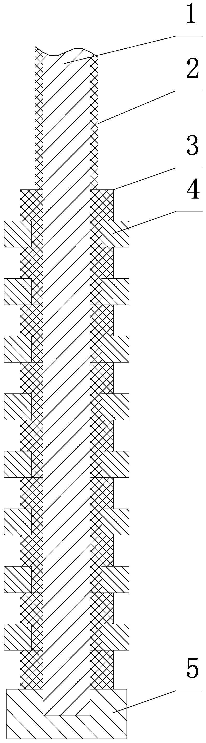
[0038] Such as figure 1 As shown, a sample mounting device for lead-bismuth alloy melt corrosion test, the mounting device includes a mounting post 1 for mounting the sample 4, and also includes a mounting post 1 for mounting the sample 4 on the axis of the mounting post 1 Position restraint restraint device;
[0039] The restraint device includes a plurality of isolation rings 3, and the isolation rings 3 can be sleeved on the mounting post 1;
[0040] The restraint device also includes a sleeve 2 that can be sleeved on the mounting post 1;
[0041] The restraining device further includes a first restraining body arranged at the bottom end of the mounting column 1, and the side surface of the first restraining body is convex relative to the side wall of the mounting column 1.
[0042] The characteristics of the traditional lead-bismuth corrosion test method are as follows: The ceramic crucible has a small volume and satisfies a higher surface dissolution ratio (the ratio of the exposed area of ​​the sample 4 to the solution, such as 35ml/cm 2 Under the condition of ), the number of sample 4 installed is small: sample 4 is generally screwed to the lower end of the mounting column 1 (usually using a screw) to ensure that the nut sample 4 (set as sample 4 with a through internal threaded hole) In close cooperation with the screw, the screw thread of the screw cap sample 4 is usually greater than 3, so in order to meet the connection requirements, the length of the sample 4 is required to be larger (usually 10mm), which limits the installation of the sample 4 on the column 1. The number of installations on the Therefore, the current lead-bismuth immersion test method has low test efficiency, and it is difficult to carry out long-term immersion and staged sampling tests of multiple parallel samples 4.
[0043] This solution provides a sample 4 restraint structure used in the lead-bismuth alloy melt corrosion test: in specific applications, the sample 4 is set as a sheet with a central hole, the isolation ring 3, the test The sample 4 and the casing 2 are sleeved on the mounting column 1, and a sample 4 is clamped between the adjacent isolation rings 3. The upper side of the uppermost isolation ring 3 has a casing that contacts the upper end of the isolation ring 3. 2;
[0044] The upper end surface of the first constraining body is used to constrain the lowest position of the layer structure formed by the casing 2, the isolation ring 3, and the sample 4 on the axis of the mounting column 1;
[0045] At the same time, downward pressure is applied to the uppermost casing 2 so that the layer structure is clamped and the lower end is supported on the first constraining body. For example, the device for applying pressure includes a second constraining body. Used to apply downward pressure to the upper end of the layer structure. In the specific application, the experimental object is limited to the sample 4, so the upper end of the uppermost casing 2 can be positioned above the liquid level of the lead-bismuth alloy melt, so the selection of the second restraint is relatively free, and multiple types can be selected Constraints, such as springs, pressure blocks, telescopic rods, etc.
[0046] In this way, the above sample 4 installation device provides a new sample 4 installation form. In specific applications, compared with the existing sample 4 connection mode, the isolation ring 3 makes two adjacent samples 4 spaced apart. That is, not only the thickness of the sample 4 is not limited to the number of threads required to complete a reliable thread connection, but also the thickness of the spacer ring 3 only needs to satisfy the above interval arrangement. In this way, since the present invention can use the thin sample 4, it can effectively reduce the single sample 4 to meet the test requirements under the premise that the test sleeve is set on the mounting post 1 to ensure the reliability of the sample 4 The minimum thickness and the exposed area of ​​sample 4 significantly increase the number of installations of sample 4 of the lead-bismuth corrosion test device, and improve the ability of the lead-bismuth corrosion test device to carry out multiple parallel sample 4 long-period immersion tests.
[0047] In the prior art, in order to consider the reliability of the installation on the restraint sample 4, the above screw is generally made of stainless steel. During the lead-bismuth corrosion test, the lead-bismuth alloy melt has a certain corrosiveness to the mounting column 1 itself. In this solution, for the combination formed by the mounting column 1, the sample 4, the isolation ring 3, and the sleeve 2, most or all of the exposed parts of the outer wall of the combination can be the outside of the sample 4, the outside of the isolation ring 3 and On the outside of the casing 2, the installation column 1 is partially exposed in the lead-bismuth alloy melt compared with the existing connection method. The installation column 1 is wrapped by the sample 4, the isolation ring 3, and the casing 2 based on the lead-bismuth alloy melting. The poor fluidity of the body itself can also effectively reduce or avoid the wear of the installation column 1 due to corrosion during use without special sealing and isolation measures.

Example Embodiment

[0048] Example 2:
[0049] Such as figure 1 As shown, this embodiment is further limited on the basis of Embodiment 1:
[0050] The outer shape of the isolating ring 3 is a stepped shaft with a diameter at one end greater than the diameter of the other end, and a journal with a length greater than the thickness of the sample 4 is also provided on the isolating ring 3. With this solution, in specific applications, the sleeve 2 is set to be less than or equal to the length of the journal. For each sample 4, one end of the sample 4 is restrained by the shoulder and the larger end of the other spacer ring 3 is used to restrain the sample. At the other end of 4, through the formation of annular surface contact or annular line contact, in the radial direction of the mounting column 1, the lead-bismuth alloy melt-proof sealing of the mating surface between the sample 4 and the isolating ring 3 is achieved; at the same time, this In the solution, the restraint of the inside of the hole of the sample 4 by the outer side of the spacer ring 3 can effectively ensure the restraint stability of the sample 4 by the device. In order to further optimize the stability, it is preferably set as follows: the journal adopts a transition journal with a gradually changing diameter; the length of the journal is equal to the thickness of the sample 4; the journal is an equal diameter journal, and the specific size is The inner diameter of sample 4 is equal, and the length of the journal is equal to the thickness of sample 4, so as to minimize the gap between sample 4 and installation column 1 after sample 4 is installed, and further optimize to avoid the penetration of lead-bismuth alloy melt The effect of sample 4 inside.
[0051] As a specific implementation form that can prevent the isolation ring 3 and the sleeve 2 from being affected by the lead-bismuth alloy melt, it is set as follows: the isolation ring 3 and the sleeve 2 are made of ceramic. In the specific application of this solution, the casing 2 and the isolation ring 3 are both ceramic tubes. After being combined with the sample 4, the installation column 1 is provided with anti-corrosion protection and the isolation sample 4, and the above combination is the object. The ring 3 and the sleeve 2 are assembled on the mounting column 1, that is, a ceramic sleeve arranged at intervals is formed on the mounting column 1. The single sleeve 2 and the isolating ring 3 are a ceramic section, and multiple ceramic sections are combined to form the ceramic sleeve. The matching form enables the existing ceramic tube processing technology to meet the accuracy and cost problems of ceramic ring processing.
[0052] In order to conveniently match the installation position and the installation quantity of the sample 4 on the installation column 1, it is set as: the number of the casing 2 is multiple. With this solution, by selecting the number of sleeves 2 used and the stacking relationship of specific sleeves 2 in the layer structure, the corresponding purpose can be achieved.
[0053] As a specific solution in which the sample 4 can be disassembled and assembled from both ends of the mounting column 1, and the necessary clamping force can be obtained through the first restraining body, it is set as follows: the first restraining body is screwed on the mounting column 1 Compression nut at the bottom 5.
[0054] As an implementation solution that the compression nut 5 itself can protect the mounting column 1, it is set that: the compression nut 5 is provided with an internal threaded hole, and the internal threaded hole is a blind hole.

Example Embodiment

[0055] Example 3:
[0056] Such as figure 1 As shown, this embodiment is further limited on the basis of any one of the technical solutions provided in Embodiment 1 or 2:
[0057] This embodiment discloses a method for installing sample 4 for lead-bismuth alloy melt corrosion test. The installation device described in any one of the above is adopted to realize the installation of sample 4 on the mounting post 1. The spacer ring 3, the sample 4, and the sleeve 2 are all sleeved on the mounting column 1, and a sample 4 is clamped between adjacent spacer rings 3. The upper side of the upper isolation ring 3 has a sleeve 2 in contact with the upper end of the isolation ring 3;
[0058] The upper end surface of the first constraining body is used to constrain the lowest position of the layer structure formed by the casing 2, the isolation ring 3, and the sample 4 on the axis of the mounting column 1;
[0059] It also includes a second constraining body for applying downward pressure to the upper end of the layer structure.

PUM

PropertyMeasurementUnit
Diameter10.0mm
Length350.0mm
The inside diameter of10.0mm

Description & Claims & Application Information

We can also present the details of the Description, Claims and Application information to help users get a comprehensive understanding of the technical details of the patent, such as background art, summary of invention, brief description of drawings, description of embodiments, and other original content. On the other hand, users can also determine the specific scope of protection of the technology through the list of claims; as well as understand the changes in the life cycle of the technology with the presentation of the patent timeline. Login to view more.
Why Eureka
Try Eureka