Receiving system, laser radar with same, and echo receiving method

A receiving system and laser radar technology, applied in radio wave measurement systems, instruments, etc., can solve the problems of internal stray light, loss of receiving efficiency, high cost of array detectors, etc., and achieve cost reduction, quantity reduction, and suppression of ambient light noise Effect

Active Publication Date: 2020-02-11
HESAI TECH CO LTD
View PDF7 Cites 23 Cited by
  • Summary
  • Abstract
  • Description
  • Claims
  • Application Information

AI Technical Summary

Problems solved by technology

Array detector reception usually requires a larger-sized detector array, such as an APD or SiPM array, which is expensive and difficult to obtain commercially at present, and the cost of array detectors is very high; the scanning mechanism receives coaxially, and the effective receiving aperture is limited by the scanning mechanism Available receiving aperture, and there must be problems such as loss of receiving efficiency and internal stray light
Therefore, there is currently no good way to act as a solid-state radar system solution

Method used


Image

  • Receiving system, laser radar with same, and echo receiving method
  • Receiving system, laser radar with same, and echo receiving method
  • Receiving system, laser radar with same, and echo receiving method

Examples


Embodiment Construction

[0040] In the following, only some exemplary embodiments are briefly described. As those skilled in the art would realize, the described embodiments may be modified in various different ways, all without departing from the spirit or scope of the present invention. Accordingly, the drawings and descriptions are to be regarded as illustrative in nature and not restrictive.

[0041] In describing the present invention, it is to be understood that the terms "center", "longitudinal", "transverse", "length", "width", "thickness", "upper", "lower", "front", " Back", "Left", "Right", "Straight", "Horizontal", "Top", "Bottom", "Inner", "Outer", "Clockwise", "Counterclockwise", etc. or The positional relationship is based on the orientation or positional relationship shown in the drawings, which is only for the convenience of describing the present invention and simplifying the description, rather than indicating or implying that the referred device or element must have a specific orie...


PUM


Abstract

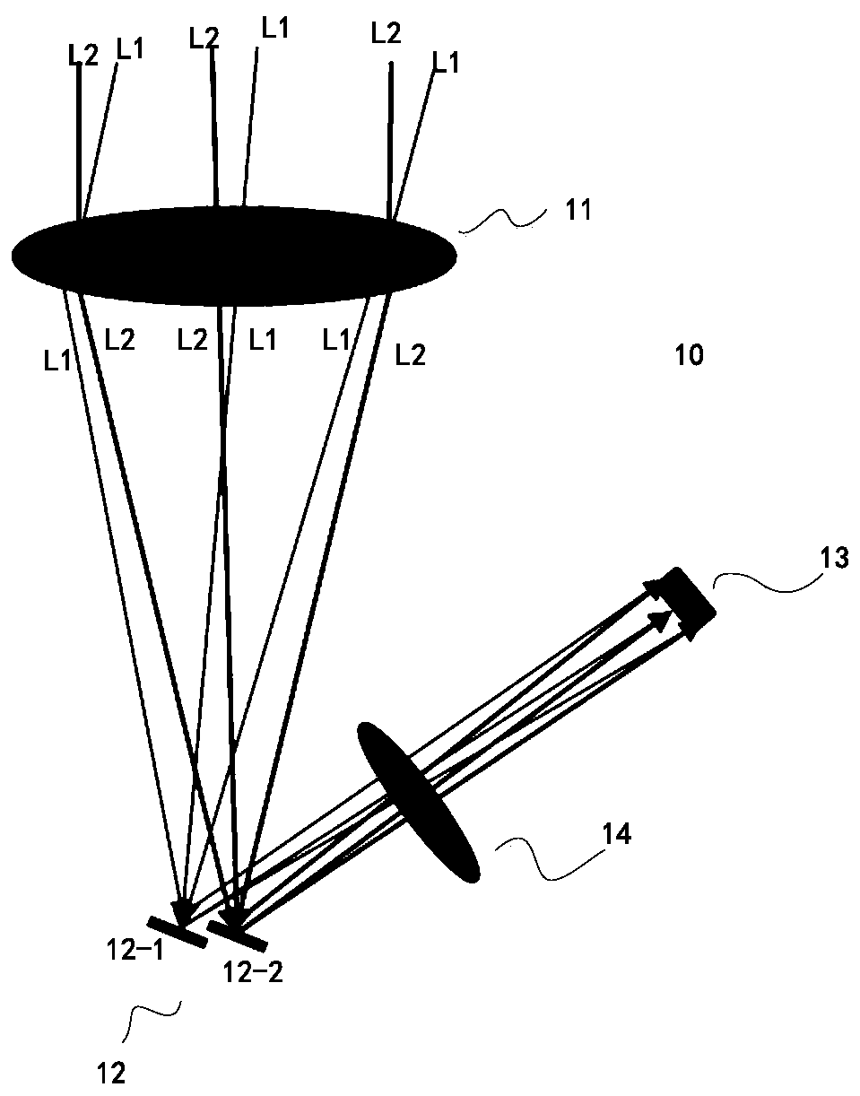
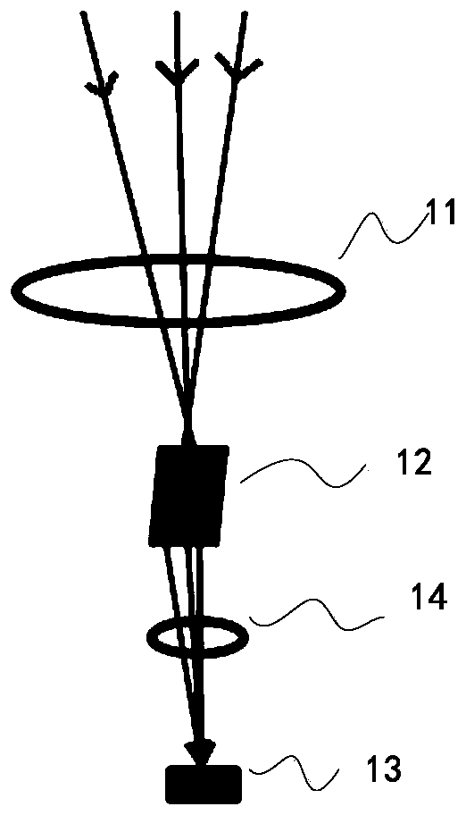
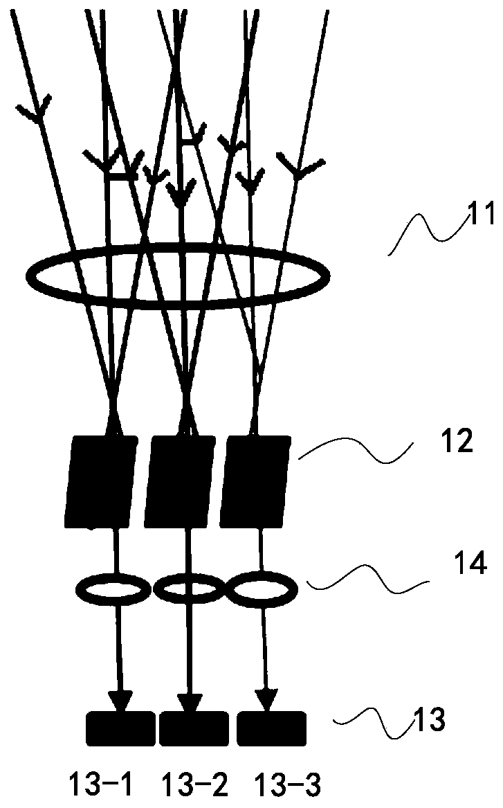
The invention relates to a receiving system which can be applied to a laser radar. The system comprises a receiving lens which is configured to receive and converge light beams reflected by an obstacle; an optical modulator having an ON state and an OFF state, disposed at the downstream of an optical path of the receiving lens, and receiving the light beams converged by the receiving lens; and a detector arranged at the downstream of the optical modulator. In the ON state, the optical modulator is configured to allow the converged light beams to input on the detector, and the in the OFF state,the converged light beam is not allowed to input onto the detector.

Description

technical field [0001] The present invention generally relates to the field of optoelectronic technology, and in particular to a laser radar receiving system, a laser radar including the same, and a method for receiving and processing echoes of the laser radar. Background technique [0002] LiDAR is a general term for laser active detection sensor equipment. Its working principle is roughly as follows: the transmitter of the laser radar emits a beam of laser light. After the laser beam encounters an object, it returns to the laser receiver after diffuse reflection. The distance from the transmitter to the object is calculated by multiplying half the time interval between sending and receiving the signal by the speed of light. In order to achieve long-distance telemetry performance, the Lidar system needs to improve the signal-to-noise ratio. In many systems, when a detector with single-photon sensitivity such as SiPM is used for detection, the shot noise caused by ambient l...

Claims


Application Information

Patent Timeline
Patent Type & Authority Applications(China)
IPC IPC(8): G01S7/487G01S7/4912G01S7/493
CPCG01S7/487G01S7/4912G01S7/493
Inventor 吴世祥王瑞向少卿
Owner HESAI TECH CO LTD
Why Eureka
Try Eureka