Electromagnetic wave lens, antenna and antenna array
A lens antenna, electromagnetic wave technology, applied to antenna arrays, antenna arrays that are powered on separately, antennas, etc., can solve problems such as increasing construction costs, and achieve the effect of less beam overlap area, easy measurement and debugging, and reduced overlap area.
- Summary
- Abstract
- Description
- Claims
- Application Information
AI Technical Summary
Problems solved by technology
Method used
Image
Examples
Embodiment 1
[0041] This embodiment is an illustrative example of the structure of the electromagnetic wave lens of the present invention.
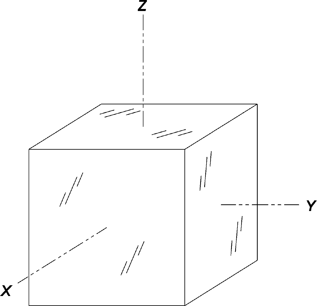
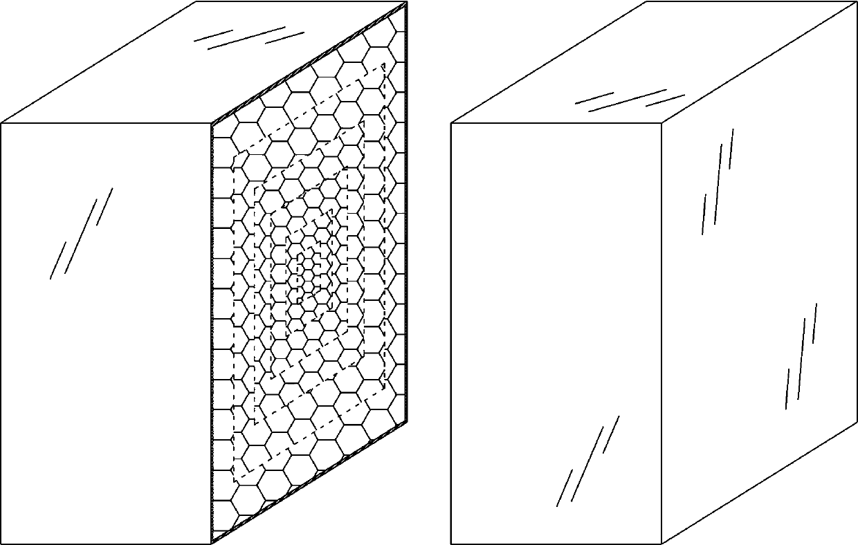
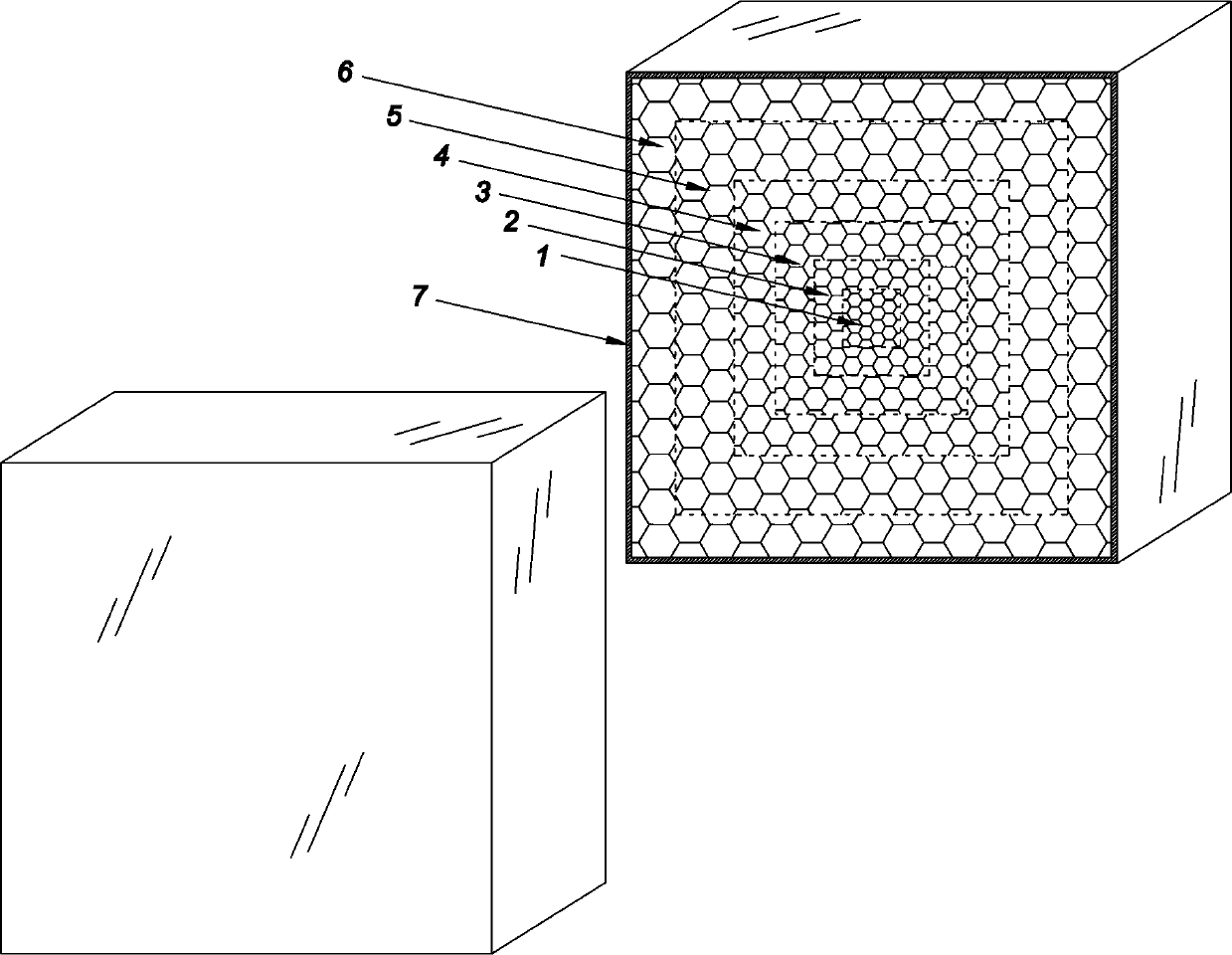
[0042] Such as figure 1 , figure 2 , image 3 , Figure 4 As shown, the electromagnetic wave lens of this embodiment includes: an inner core 7 , a first dielectric layer 1 , a second dielectric layer 2 , a third dielectric layer 3 , a fourth dielectric layer 4 , a fifth dielectric layer 5 and a shell 6 .
[0043] Such as figure 2 , image 3 , Figure 4 As shown, the first dielectric layer 1 , the second dielectric layer 2 , the third dielectric layer 3 , the fourth dielectric layer 4 , the fifth dielectric layer 5 and the shell enclose the inner core 7 layer by layer.
[0044] Wherein, the inner core body 7 is a cube within the cuboid category, and the other dielectric layers are also cubes within the cuboid category.
[0045] The target dielectric constant of the inner core body 7 is 2, while the target dielectric constant of the fifth dielect...
Embodiment 2
[0050] This embodiment is an illustrative example of the structure of the electromagnetic wave lens antenna of the present invention.
[0051] Such as Figure 5 As shown, an electromagnetic wave lens antenna in this embodiment includes: one antenna vibrator, and the antenna vibrator corresponds to one electromagnetic wave lens. The electromagnetic wave lens is the electromagnetic wave lens with the structure described in Embodiment 1. The radiation center of the antenna dipole is on the central axis of the electromagnetic wave lens, and the radiation center of the antenna dipole points to the center of the electromagnetic wave lens as the direction of the antenna.
[0052] The directivity pattern of the electromagnetic wave lens antenna in the horizontal direction and the directivity pattern in the vertical direction are substantially the same as those corresponding to the Lunberg lens antenna. but if Figure 6 As shown, the coverage area projected by the electromagnetic wa...
Embodiment 3
[0055] This embodiment is an illustrative example of the structure of the electromagnetic wave lens antenna array of the present invention.
[0056] Such as Figure 7 As shown, an electromagnetic wave lens antenna array in this embodiment includes three sets of electromagnetic wave lens antennas with structures as described in Embodiment 2. The centers of the electromagnetic wave lenses of the three sets of electromagnetic wave lens antennas are distributed on the same horizontal plane and arranged along a straight line.
[0057] Such as Figure 7 As shown, when the three sets of electromagnetic wave lens antennas are all vertically facing the bottom surface, the coverage of the electromagnetic wave lens antenna array projected to the ground in this embodiment can be regarded as the coverage of the three antennas in Embodiment 2. There is an intersection along the straight line direction. composed of stacked arrays.
[0058] Such as Figure 8 As shown, when the two sets of...
PUM
 Abstract
Description
Claims
Application Information
 - R&D
- Intellectual Property
- Life Sciences
- Materials
- Tech Scout
- Unparalleled Data Quality
- Higher Quality Content
- 60% Fewer Hallucinations
Browse by: Latest US Patents, China's latest patents, Technical Efficacy Thesaurus, Application Domain, Technology Topic, Popular Technical Reports.
© 2025 PatSnap. All rights reserved.Legal|Privacy policy|Modern Slavery Act Transparency Statement|Sitemap|About US| Contact US: help@patsnap.com


