Flyback grid-connected inverter with low frequency ripple suppression function

A ripple suppression and flyback technology, applied to output power conversion devices, DC power input conversion to DC power output, AC power input conversion to DC power output, etc., can solve problems such as low-frequency ripple of input current, Achieve the effects of eliminating low-frequency ripple, realizing power decoupling, and realizing maximum power point tracking

Pending Publication Date: 2020-02-11
陈仲
View PDF4 Cites 2 Cited by
  • Summary
  • Abstract
  • Description
  • Claims
  • Application Information

AI Technical Summary

Problems solved by technology

But at the same time, the flyback inverter also has the problem of input current low-frequency ripple

Method used


Image

  • Flyback grid-connected inverter with low frequency ripple suppression function
  • Flyback grid-connected inverter with low frequency ripple suppression function
  • Flyback grid-connected inverter with low frequency ripple suppression function

Examples


Embodiment Construction

[0016] Below in conjunction with accompanying drawing, the technical scheme of invention is described in detail:

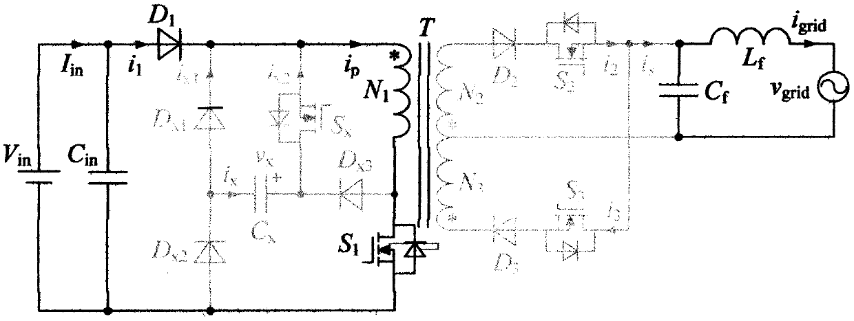
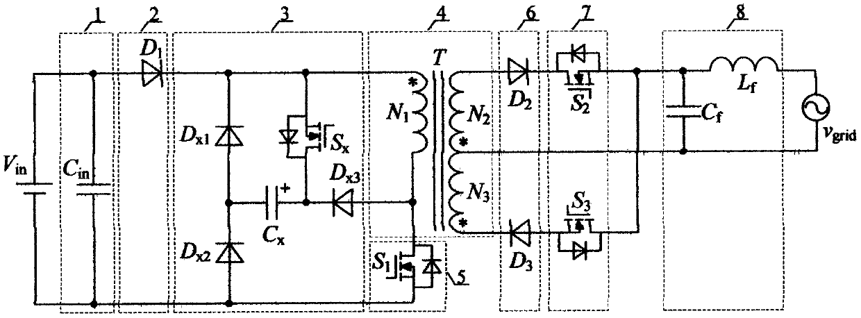
[0017] attached figure 1 Shown is a flyback grid-connected inverter with low-frequency ripple suppression. by the input DC supply V in , Input capacitor 1, input diode 2, active decoupling circuit 3, isolation transformer 4, primary side switch tube 5, secondary side diode 6, secondary side switch tube 7, output filter circuit 8 and power grid. C in is the input capacitance, D 1 is the input diode, T is the isolation transformer, N 1 is the primary winding of the isolation transformer, N 2 , N 3 is the secondary winding of the isolation transformer, S 1 is the primary switch tube, D 2 、D 3 is the secondary diode, S 2 , S 3 is the secondary switch tube, C f is the output filter capacitor, L f is the output filter inductance, v grid is the grid voltage, C x is the decoupling capacitor, D x1 ~D x3 is the decoupling diode, S x Is the decoupling switc...


PUM


Abstract

The invention discloses a flyback grid-connected inverter with a low frequency ripple suppression function. The main circuit topology of the inverter includes an input DC power supply, an input capacitor, an input diode, an active decoupling circuit, an isolation transformer, a primary switching tube, a secondary diode, a secondary switching tube, an output filter circuit and a power grid. The output pulsating power is completely transferred to the decoupling capacitor by additionally arranging the active decoupling circuit on the basis of the traditional single-stage flyback grid-connected inverter structure so as to realize the suppression of the low frequency ripple of the input current and achieve the purpose of eliminating the high-capacity and short-life electrolytic capacitor.

Description

technical field [0001] The invention relates to a flyback grid-connected inverter with a low-frequency ripple suppression function, which belongs to a micro-inverter, in particular to a micro-inverter with a power decoupling function, which realizes low-frequency ripple of input current Elimination, suitable for new energy power generation fields such as photovoltaics, which can realize maximum power point tracking (MPPT) of photovoltaic panels. Background technique [0002] In the new energy grid-connected power generation system, the grid-connected current is required to be synchronized with the grid voltage, so there is twice the power frequency pulsation in the instantaneous output power, and this pulsating power will propagate to the DC input side, making the input current also contain twice the frequency the exchange component. The low-frequency ripple of the current will make it difficult for the photovoltaic panel to track its maximum power point and affect its powe...

Claims


Application Information

Patent Timeline
Patent Type & Authority Applications(China)
IPC IPC(8): H02J3/38H02M1/14H02M7/5387H02M3/335
CPCH02M1/14H02M7/53871H02M3/33523H02M3/33576
Inventor 陈仲章修齐许亚明王傲雪
Owner 陈仲
Why Eureka
Try Eureka