Manipulator capable of controlling clamping force and measuring distance between clamping points

A gripping point and gripping force technology, applied in the field of manipulators that control the gripping force and measure the spacing between gripping points, and can solve problems such as lack of manipulators

Active Publication Date: 2020-02-14
CHINA ACAD OF ART
View PDF5 Cites 2 Cited by
  • Summary
  • Abstract
  • Description
  • Claims
  • Application Information

AI Technical Summary

Problems solved by technology

In the mechanical industry, length measurement is the most common measurement, but so far, there is still a lack of manipulators capable of dimension measurement

Method used


Image

  • Manipulator capable of controlling clamping force and measuring distance between clamping points
  • Manipulator capable of controlling clamping force and measuring distance between clamping points
  • Manipulator capable of controlling clamping force and measuring distance between clamping points

Examples


Embodiment Construction

[0071] Below in conjunction with accompanying drawing this design is described further.

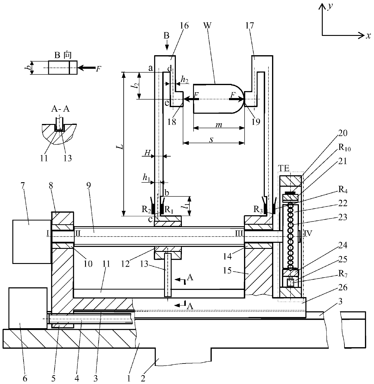
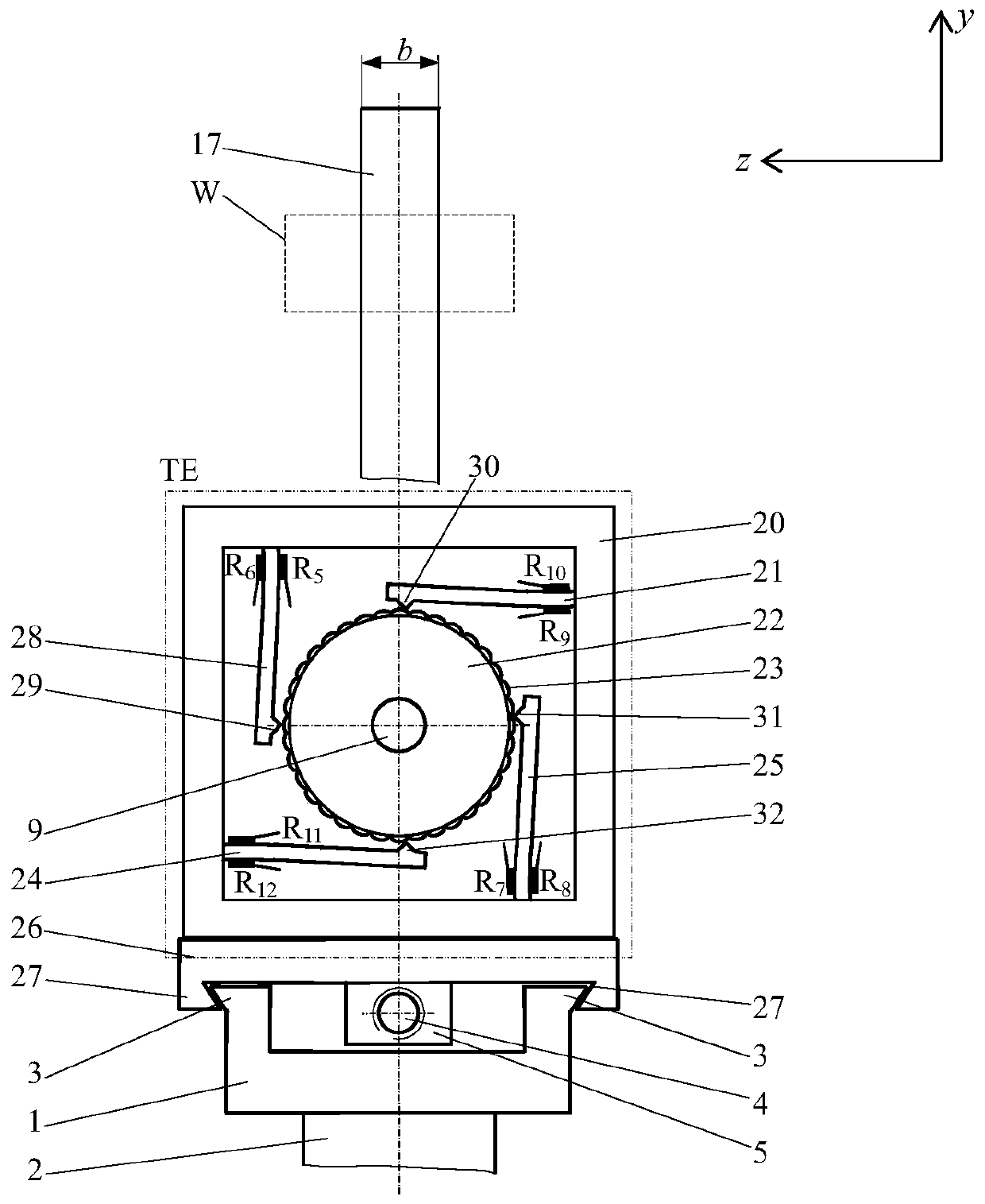
[0072] refer to Figure 1-Figure 6 , this design is a manipulator that controls the clamping force and measures the distance between clamping points. This manipulator is made up of guide rail seat 1, sliding frame 26, power transmission shaft 4, coding screw mandrel, driver, clamping arm and numerical control device.

[0073] The structure of the guide rail seat 1 includes a rectangular thick base plate, a coupling 2 and parallel male guide rails 3 . Coupling 2 is fixed under the thick base plate and is used to connect the arm of the robot. The parallel male guide rails 3 are located on the front and rear sides of the upper surface of the thick substrate.

[0074] The structure of the sliding frame 26 includes a rectangular bottom plate, parallel female guide rails 27 positioned at the front and rear edges of the bottom bottom plate, a protrusion 5 with a threaded through hole position...


PUM


Abstract

The invention discloses a manipulator capable of controlling clamping force and measuring distance between clamping points. The manipulator is used for an industrial robot. The manipulator is composedof a clamping arm, an encoding lead screw, a rack, actuators and a numerical controller. The clamping arm comprises a movable arm and a fixed arm which have the force and deformation sensing function. The encoding lead screw is composed of a micrometering lead screw and a three-state encoder. The three-state encoder comprises a fluted disk and a cantilever beam sensor. The clamping arm and the encoding lead screw constitute a force-deformation-displacement combined sensing mechanism which is mounted on the rack. The numerical controller controls the clamping arm to clamp an object through theactuators and the encoding lead screw. The combined sensing mechanism and the numerical controller mutually transmit measurement control signals. The numerical controller controls clamping force andgives the distance between the clamping points.

Description

technical field [0001] This design is a manipulator that controls the clamping force and measures the distance between clamping points, and is used for industrial robots. Background technique [0002] The manipulator is the front-end operating mechanism of a variety of robots. It is generally installed on the robotic arm of the robot. Its basic function is to pick and place, that is, to grab, transfer, and release objects. During the pick-and-place process, it is necessary to control the clamping force of the manipulator on the object. To configure manipulators for robots including a large number of automated production, processing, and testing equipment in the industrial field, in addition to the pick-and-place function, it is also necessary to add other functions according to different tasks, such as measurement, identification, assembly, adjustment, etc. In the mechanical industry, length measurement is the most common measurement, but so far, there is still a lack of ma...

Claims


Application Information

Patent Timeline
Patent Type & Authority Applications(China)
IPC IPC(8): B25J13/08
CPCB25J13/085B25J13/088B25J13/082B25J15/026
Inventor 鲁阳胡惠君倪嘉昊沈建李昕
Owner CHINA ACAD OF ART
Why Eureka
Try Eureka